Multiple-effect heat pipe type distillation column driven by condensation steam source heat pump

A technology of heat pipe type and source heat pump, which is applied in the direction of tubular distiller, heat recovery system, multi-stage water treatment, etc., and can solve problems such as difficult maintenance, high maintenance cost, and expensive water vapor compressor

Inactive Publication Date: 2018-08-10
侴雨宏 +1
View PDF7 Cites 1 Cited by
  • Summary
  • Abstract
  • Description
  • Claims
  • Application Information

AI Technical Summary

Problems solved by technology

[0004] However, the shortcomings of the compressed steam distillation device also restrict its further development: (1) the price of the steam compressor is extremely expensive, and the oil-free technology is relatively complicated, resulting in reduced product reliability and difficult maintenance; (2) the device is a large-scale chemical equipment, Therefore, it is difficult to achieve miniaturization and household appliances; (3) neither the corrosion of the secondary steam to the water vapor compressor nor the corrosion of the water vapor compressor to the secondary steam can be avoided, and it is especially suitable for handling corrosive solutions and preparing High-standard injection; (4) Since the inflection point of the chemical activity of water is 60°C, for corrosive solutions or heat-sensitive materials, a low-temperature distillation process below 60°C must be used, and due to the low density of water vapor in vacuum, As a result, the suction displacement and cost of the water vapor compressor are hundreds of times higher than that of the heat pump compressor, resulting in extremely poor economy, slow delivery time, high maintenance costs, and are not suitable for handling corrosive solutions and heat-sensitive materials; ( 5) It is impossible to realize the distillation process with full temperature range and full capacity range

Method used


Image

  • Multiple-effect heat pipe type distillation column driven by condensation steam source heat pump

Examples


Embodiment Construction

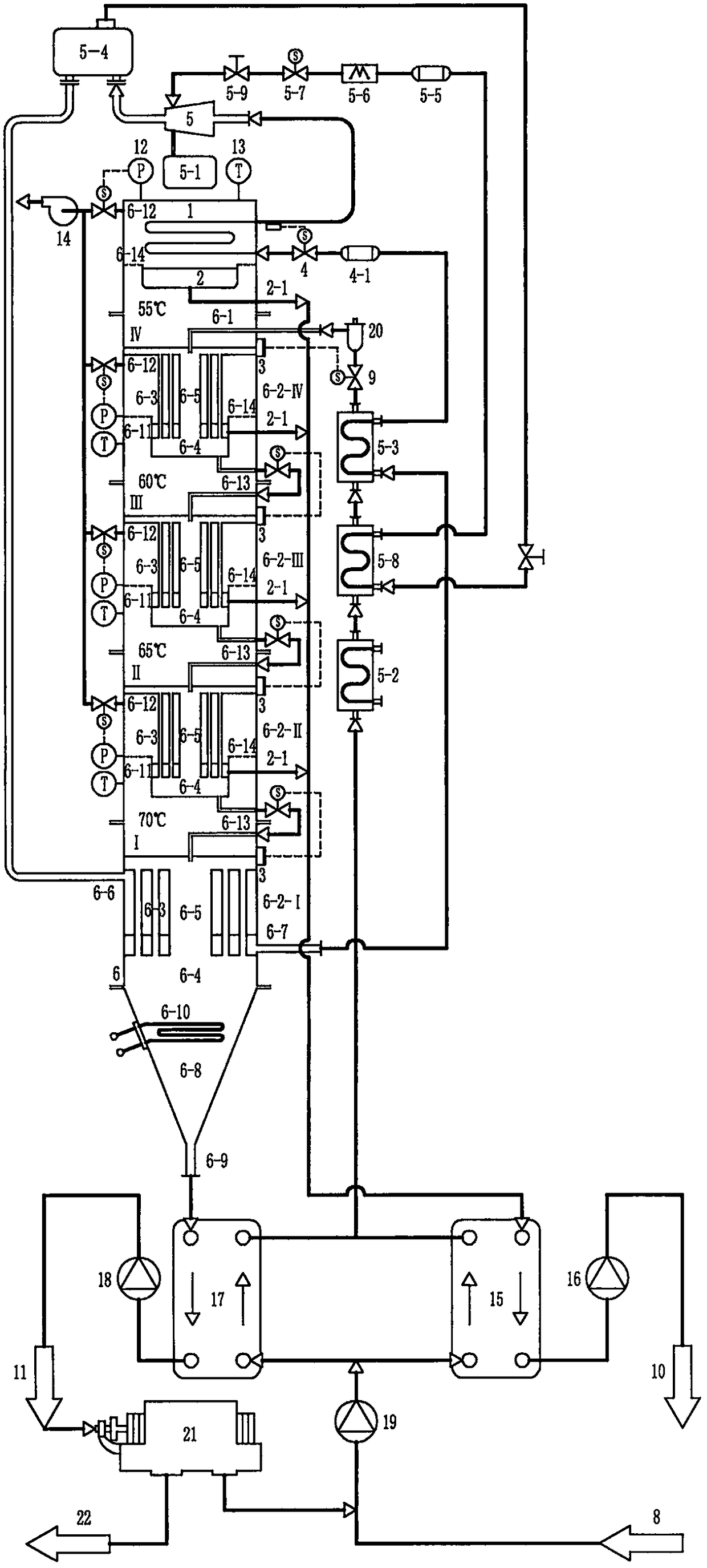
[0065] The embodiment of the multi-effect heat pipe distillation column driven by the condensation source heat pump proposed by the present invention is attached figure 1 As shown, the description is as follows: the evaporator 1 is made of copper tubes with 664kW of evaporative heat, horizontally installed; 0.3m3 fresh water tank 2; the stainless steel fresh water tube 2-1 with a diameter of 10mm / wall thickness of 1mm / total length 1600mm ;Stainless steel liquid level switch 3 with elevation 100mm; copper thermal expansion valve 4 with interface diameter 60mm / wall thickness 1mm; copper dry filter 4-1 with interface diameter 60mm / wall thickness 1mm; compressor 5 with suction capacity 600m3 / h ;Gas internal combustion engine 5-1 with an output shaft power of 109kW; cylinder liner regenerator 5-2 with cylinder liner cooling and flue gas regenerating capacity of 109kW; subcooling regenerator 5-3 with regenerating capacity of 33kW; Separator 5-4; copper oil filter 5-5 with interface ...


PUM


Abstract

The invention provides a multiple-effect heat pipe type distillation column driven by a condensation steam source heat pump. The multiple-effect heat pipe type distillation column driven by a condensation steam source heat pump integrates a condensation steam source heat pump, a heat pipe heat exchanger and multiple-effect distillation technology to form a whole system, and is a cross-boundary product of a heat pump industry, a heat exchange industry and a distillation industry; condensation latent heat of last effect secondary steam is recovered by using the condensation steam source heat pump, and a condenser independently provides the heat source required for first effect distillation; through the superposition of open type multi-stage heat pipes, countercurrent heat change and single-tower and multi-effect distillation technology are realized, and secondary steam condensation latent heat is utilized by effect in order; an integrated design of the condenser, the multiple-effect heattubular type distillation column and an evaporator is realized; and the multiple-effect heat tubular type distillation technology driven by the condensation steam source heat pump is realized.

Description

(1) Technical field [0001] The invention relates to a condensate source heat pump driven multi-effect heat pipe type used in seawater desalination, food processing, beverage production, sewage treatment, water purification treatment, reclaimed water treatment, chemical industry, household water purification, commercial water purification, and household appliances. distillation tower. (2) Background technology [0002] Compressed vapor distillation device: Seawater is heated on the evaporation side of the evaporative condenser to distill secondary steam, which is compressed by the water vapor compressor to increase the pressure and temperature, and then re-entered into the condensing side of the evaporative condenser to be condensed as heating steam. The latent heat of condensation of fresh water is recovered at the same time to provide the latent heat of seawater distillation for its evaporation side, so that the driving energy consumption of the device is minimized; in addi...

Claims


Application Information

Patent Timeline
IPC IPC(8): B01D3/04C02F9/10C02F1/08C02F103/08
CPCB01D3/04C02F1/001C02F1/08C02F1/38C02F9/00C02F2103/08C02F2301/08Y02B30/52
Inventor 侴雨宏王娜
Owner 侴雨宏
Why Eureka
Try Eureka