Partitioned ammonia spraying adjustment and control method of SCR (Selective Catalytic Reduction) denitration device

An adjustment control and denitrification technology, which is applied in separation methods, chemical instruments and methods, and separation of dispersed particles, can solve problems such as difficulty in ensuring real-time measurement and affecting the quality of leveling valves in ammonia injection zones, so as to eliminate adverse effects and improve Quality, the effect of reducing ammonia slip rate

Active Publication Date: 2018-08-10
浙江兴核智能控制技术有限公司
View PDF6 Cites 19 Cited by
  • Summary
  • Abstract
  • Description
  • Claims
  • Application Information

AI Technical Summary

Problems solved by technology

However, only with the above-mentioned technical solution, since the NOx concentration at the outlet of the downstream SCR will not change immediately after increasing or decreasing the am

Method used


Image

  • Partitioned ammonia spraying adjustment and control method of SCR (Selective Catalytic Reduction) denitration device
  • Partitioned ammonia spraying adjustment and control method of SCR (Selective Catalytic Reduction) denitration device

Examples


Embodiment 1

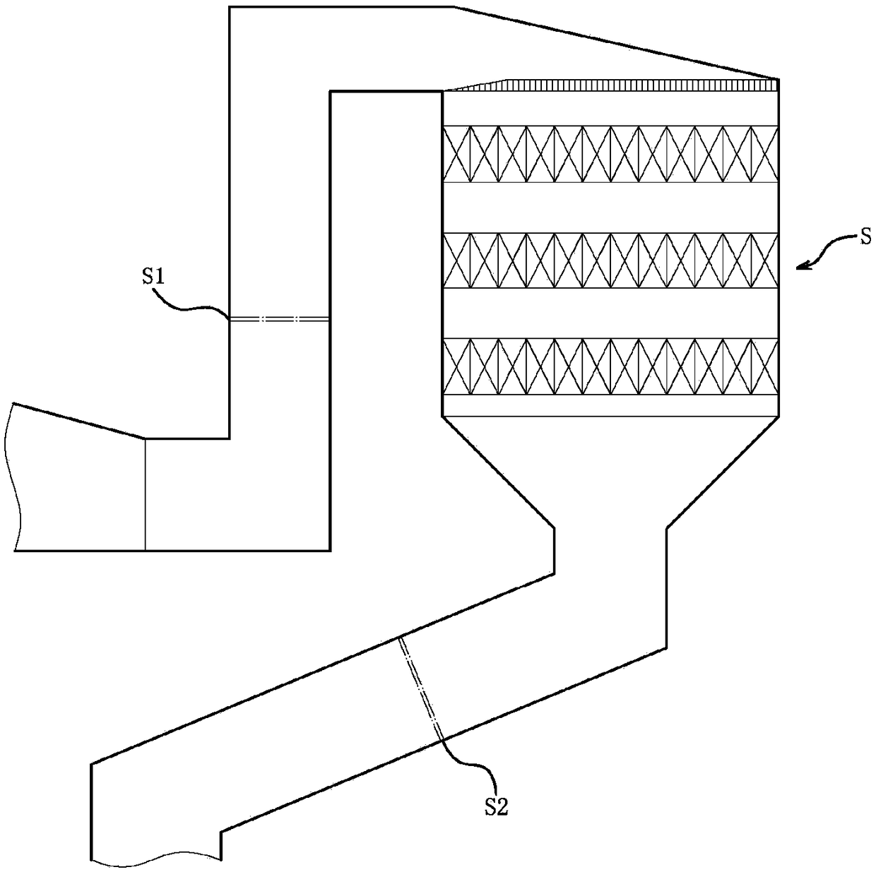
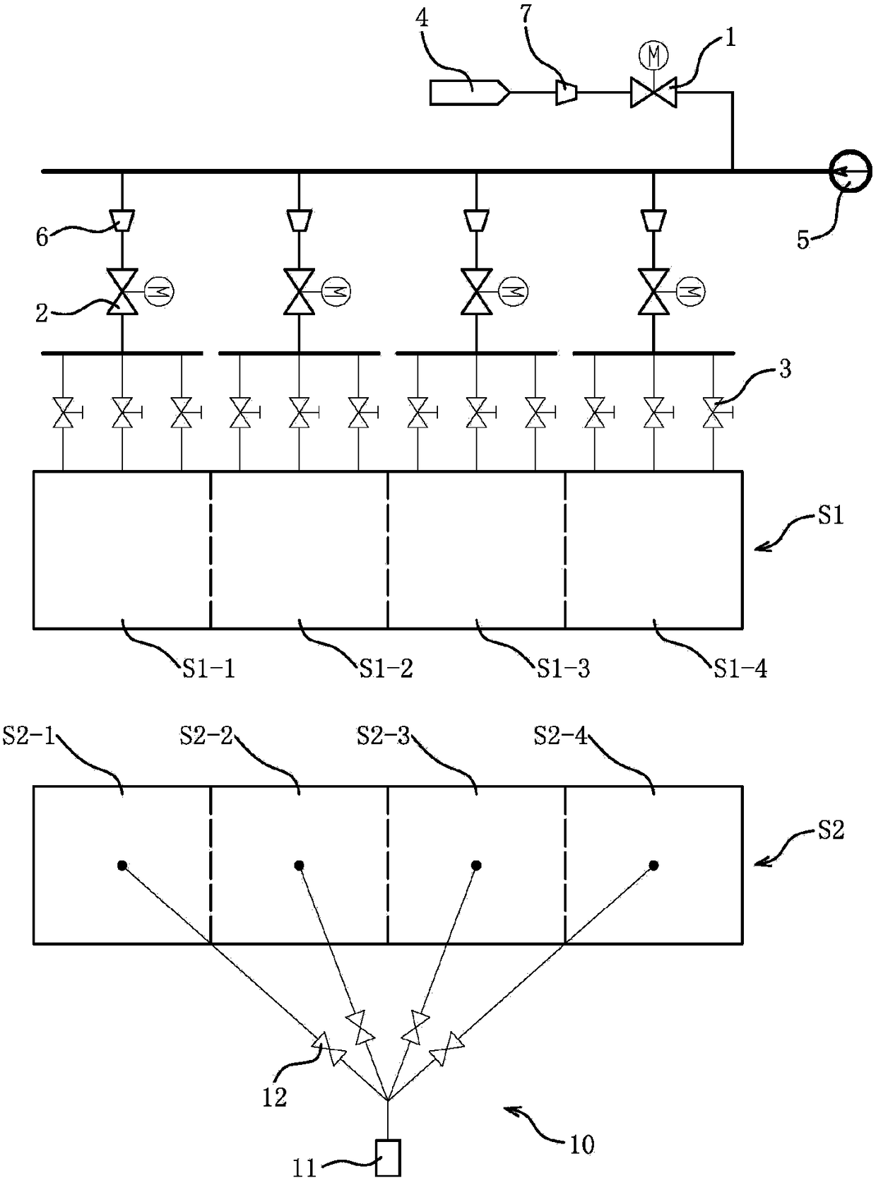
[0032] The 600MW coal-fired unit adopts SCR denitrification device to reduce the NOx emission concentration in the flue gas. The reducing agent is liquid ammonia. According to the technical scheme, the inlet ammonia injection section and the outlet measurement section are virtually divided into four sections of the same size, and the section size of each section is 3.6m×3.2m.

[0033] For example, a set of CEMS instruments is installed at the inlet of the SCR denitrification device on each side. Under a certain working condition, the NOx concentration at the inlet of the SCR denitrification device is 350mg / Nm 3 , according to the requirements of the ultra-low emission standard, the NOx concentration control value at the outlet of the SCR denitrification device is 35mg / Nm 3 . The measured values ​​of ammonia flow in each zone at the inlet of the SCR denitrification device are 24.4, 25.6, 25.3, and 26.1kg / h, respectively, and the corresponding NOx concentrations in each zone at...

Embodiment 2

[0039] The system composition is the same as that of the implementation 1 coal-fired unit, and the technical conditions of the example are also the same. The process of determining the target value of the ammonia flow adjustment in each zone is as follows:

[0040] The initial value of the ammonia flow adjustment target in the first zone = 23.08kg / h;

[0041] The initial value of the ammonia flow adjustment target in the second zone = 25.20kg / h;

[0042] The initial value of the ammonia flow adjustment target in the third zone = 25.88kg / h;

[0043] The initial value of the ammonia flow adjustment target in the fourth zone = 27.87kg / h.

[0044] Initial value correction factor=(24.4+25.6+25.3+26.1)÷(23.08+25.20+25.88+27.87)=0.9938

[0045] The target value of ammonia flow adjustment in the first zone = 23.08 × 0.9938 = 22.94kg / h;

[0046] The target value of ammonia flow adjustment in the second zone = 25.20 × 0.9938 = 25.04kg / h;

[0047] The target value of ammonia flow adj...


PUM


Abstract

The invention discloses a partitioned ammonia spraying adjustment and control method of an SCR (Selective Catalytic Reduction) denitration device. A partitioned ammonia flow measured value is used asa closed-loop signal for adjusting and controlling an ammonia spraying partitioned leveling valve. According to the partitioned ammonia spraying adjustment and control method of the SCR denitration device, disclosed by the invention, important parameters including inlet NOx concentration, outlet partitioned NOx concentration, a total ammonia spraying amount, partitioned ammonia flow and the like of the SCR denitration device are monitored, and the partitioned ammonia flow measured value is used as the closed-loop signal for adjusting and controlling the ammonia spraying partitioned leveling valve, so that the online adjustment quality of partitioned ammonia spraying is improved and the ammonia escaping rate is reduced, and furthermore, adverse effects, caused by ammonia escaping, on downstream equipment of the SCR denitration device are alleviated, even eliminated.

Description

technical field [0001] The invention relates to a method for regulating and controlling ammonia spraying in different areas of an SCR denitrification device, and belongs to the field of flue gas denitrification of large coal-fired power stations. Background technique [0002] At present, large coal-fired power plants generally use SCR denitrification devices to reduce the concentration of NOx emissions in flue gas. SCR utilizes NH 3 The reduction characteristics of NOx, under the action of the catalyst, NOx is reduced to N which is harmless to the environment 2 and H 2 O. In the actual operation process, the control of the amount of ammonia injection is particularly critical. Increasing the amount of ammonia injection is beneficial to reduce the concentration of NOx emissions, but the ammonia slip rate will increase accordingly, which will easily cause the downstream air preheater to be blocked and corroded due to the deposition of ammonium bisulfate , It may also cause ...

Claims


Application Information

Patent Timeline
IPC IPC(8): B01D53/90B01D53/56
CPCB01D53/8625B01D53/8696B01D53/90B01D2251/2062B01D2258/0283
Inventor 韦红旗石伟伟
Owner 浙江兴核智能控制技术有限公司
Why Eureka
Try Eureka