Multi-section roll-in grinding system with multiple material bed characteristics

A technology of roller pressing and material bed, which is applied in the direction of grain processing, etc., can solve the problems of unqualified product performance, etc., and achieve the effects of high energy utilization rate, increased sphericity, and reduced particle size

Active Publication Date: 2018-08-10
成都建筑材料工业设计研究院有限公司
View PDF6 Cites 0 Cited by
  • Summary
  • Abstract
  • Description
  • Claims
  • Application Information

AI Technical Summary

Problems solved by technology

[0006] The purpose of the present invention is: in order to further reduce the power consumption of the cement grinding system, and at the same time solve the problem of unqualified product performance of the cement final grinding system of the roller press, the present invention proposes a multi-stage rolling grinding system with the characteristics of a multi-material bed. The grinding mechanism of the machine is all based on the material bed grinding mechanism, especially suitable for cement grinding, which can further reduce the power consumption of the cement grinding process while ensuring the performance of the finished cement product

Method used


Image

  • Multi-section roll-in grinding system with multiple material bed characteristics
  • Multi-section roll-in grinding system with multiple material bed characteristics
  • Multi-section roll-in grinding system with multiple material bed characteristics

Examples


Embodiment 1

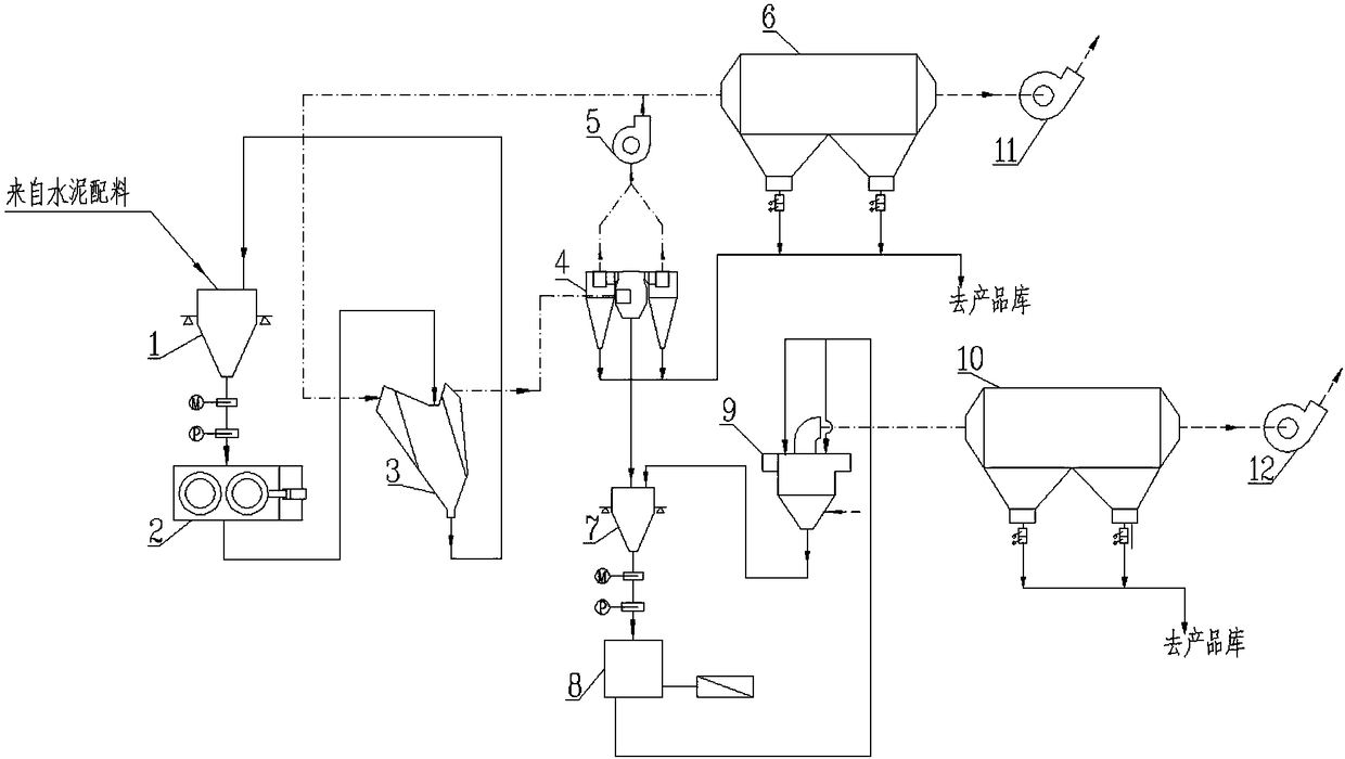
[0027] refer to figure 1 As shown, a two-stage roller press cement grinding system with a multi-material bed feature includes a first-stage roller press and a second-stage roller press. One-stage roller press includes belt conveyor, elevator, one-stage steady flow bin 1, one-stage roller press 2, static powder separator 3, coarse powder separator 4, circulation fan 5, one-stage dust collector 6 and one-stage exhaust fan 11 The second-stage roller press includes an elevator, a chute, a second-stage steady flow bin 7, a second-stage roller press 8, a fine powder separator 9, a second-stage dust collector 10, and a second-stage exhaust fan 12. Belt conveyors, elevators, and chutes are used to convey materials, and are set up according to the specific plant layout, which are not marked in the figure.

[0028] By setting a belt conveyor and a hoist, the first section of steady flow bin 1, the first section of roller press 2, and the static powder separator 3 are sequentially conne...

Embodiment 2

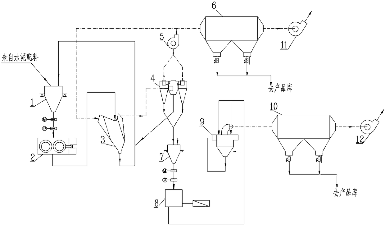
[0034] as attached figure 2 As shown, the present embodiment is basically the same as Embodiment 1, and its feature is that: the fine particle material (fineness requirement is generally specific surface area ≥ 2000) selected by the coarse powder separator 4 enters the second stage steady flow bin 7, and the coarse particle The material enters a stable flow warehouse. In this embodiment, the hoist, the chute, the second-stage steady flow bin 7, the second-stage roller press 8, and the fine powder separator 9 of the second-stage rolling press are connected in sequence to form a loop. The fine powder separator 9, the second-stage dust collector 10, and the second-stage exhaust fan 12 are connected successively. A feeding port of the second section of steady flow bin 7 is connected with the 4 fine particle outlets of the coarse powder separator of a roller press, and the coarse particle outlet of the coarse powder separator 4 is connected with one section of steady flow bin 1, ...

Embodiment 3

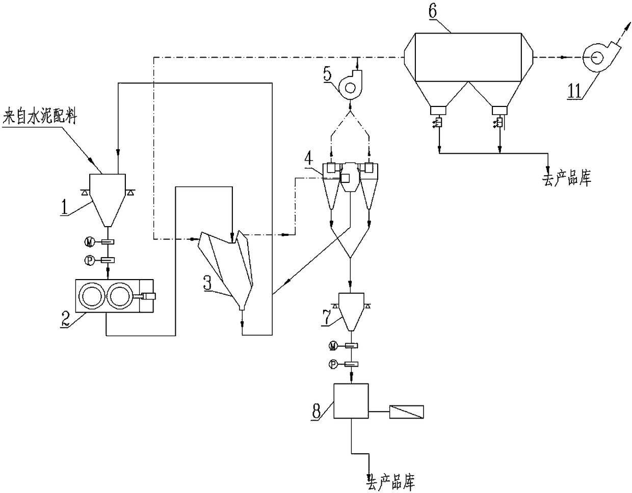
[0037] as attached image 3 As shown, the present embodiment is basically the same as Embodiment 1, and is characterized in that: the fine particle material (fineness requirement is generally specific surface area ≥ 3000) selected by the coarse powder separator 4 enters the second stage steady flow bin 7, and the coarse particle The material enters the first-stage steady flow bin 1, and then enters the second-stage roller press. After being rolled by the second-stage roller press, it directly enters the product warehouse. The fine powder separator 9, the second-stage dust collector 10 and the second-stage tail Exhaust fan 12. In this embodiment, the second-stage steady flow bin 7 and the second-stage roller press machine 8 of the second-stage rolling press are connected in sequence to form an open circuit process. A feeding port of the second section of steady flow bin 7 is connected with the 4 fine particle outlets of the coarse powder separator of a roller press, and the co...


PUM


Abstract

The invention discloses a multi-section roll-in grinding system with multiple material bed characteristics, and belongs to the field of material grinding systems. The multi-section roll-in grinding system comprises multiple sections of roll-in from one to N, wherein N is an integer larger than or equal to 2. The first section of roll-in comprises a first-section current stabilizing bin, a first-section roll-in machine, a static powder concentrator, a coarse powder concentrator, a circulating fan, a first-section dust collector and a first-section tail exhaust fan. The second section of roll-incomprises a second-section current stabilizing bin, a second-section roll-in machine, a fine powder concentrator, a second-section dust collector and a second-section tail exhaust fan. The N sectionsof roll-in after the second section of roll-in all repeat the second section of roll-in before the N sections of roll-in. The material bed grinding mechanism is adopted for all material grinding, themulti-section roll-in grinding system is especially suitable for cement grinding, and the power consumption of cement grinding procedures can be further reduced under the condition that the finishedcement performance is guaranteed.

Description

technical field [0001] The invention belongs to the field of material grinding systems, and particularly relates to the grinding of raw materials such as cement clinker, setting-adjusting materials and mixed materials for the cement industry. Materials, concrete admixtures and other materials that need to be ground in the industrial field. Background technique [0002] Material grinding is an operation with extremely low energy efficiency. Taking the cement production process as an example, the power consumption of the grinding process accounts for about 65% to 70% of the total power consumption of the entire cement production, of which the cement grinding process accounts for about 30%. Therefore, vigorously reducing the power consumption of the cement grinding process is of great significance to the cost control, energy saving and emission reduction of cement enterprises. At present, in the cement grinding system, the main equipments used for crushing and grinding are bal...

Claims


Application Information

Patent Timeline
Patent Type & Authority Applications(China)
IPC IPC(8): B02C21/00B02C4/02B02C15/00
CPCB02C4/02B02C15/00B02C21/00B02C2015/002
Inventor 彭林山刘建李鹏斌于波
Owner 成都建筑材料工业设计研究院有限公司
Why Eureka
Try Eureka