Supercharge Your Innovation With Domain-Expert AI Agents!

Laser projection device and mobile terminal

A laser projection and laser technology, applied in the direction of using optical devices, measuring devices, projection devices, etc., can solve the problems of laser energy loss, increase power consumption of mobile terminals, etc., and achieve the effect of avoiding loss

Active Publication Date: 2018-08-14
VIVO MOBILE COMM CO LTD
View PDF5 Cites 3 Cited by
  • Summary
  • Abstract
  • Description
  • Claims
  • Application Information

AI Technical Summary

Problems solved by technology

[0004] Embodiments of the present invention provide a laser projection device and a mobile terminal to solve the problem that part of the laser energy is absorbed by the coding shielding structure, resulting in loss of laser energy and increasing the power consumption of the mobile terminal

Method used


Image

  • Laser projection device and mobile terminal
  • Laser projection device and mobile terminal
  • Laser projection device and mobile terminal

Examples


Embodiment Construction

[0022] The following will clearly and completely describe the technical solutions in the embodiments of the present invention with reference to the accompanying drawings in the embodiments of the present invention. Obviously, the described embodiments are some of the embodiments of the present invention, but not all of them. Based on the embodiments of the present invention, all other embodiments obtained by persons of ordinary skill in the art without creative efforts fall within the protection scope of the present invention.

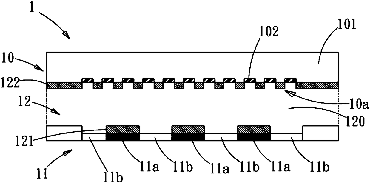
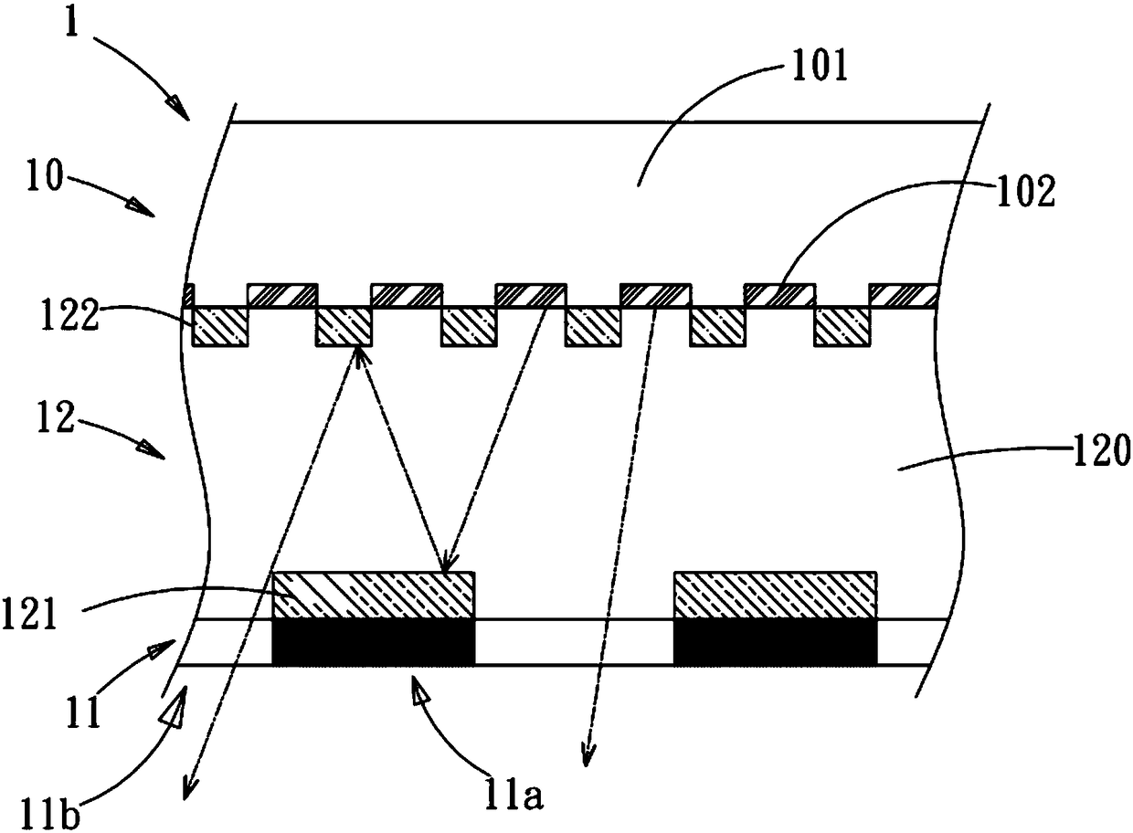
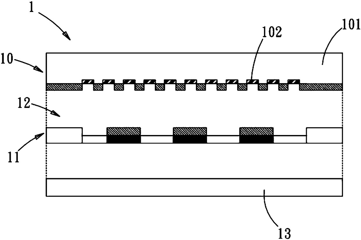
[0023] see figure 1 , figure 2 and image 3 , which is a schematic diagram of the laser projection device, a schematic diagram of the optical path, and a use state diagram of the first embodiment of the present invention; as shown in the figure, the laser projection device 1 of this embodiment includes a laser light source assembly 10, a coded shielding structure 11 and a light guide structure 12. The laser light source assembly 10 includes a base b...


PUM


Abstract

The invention discloses a laser projection device. The laser projection device comprises a laser light source component and a code shielding structure on the laser light source component, the laser light source component is provided with a plurality of light emitting points on the surface facing to the code shielding structure, the code shielding structure comprises a shielding area provided witha shielding pattern and a light transmitting area at the outside of the shielding pattern, the laser projection device further comprises a light guiding structure between the laser light source component and the code shielding structure, and the light guiding structure guides the light projected by the laser light source component to the shielding area to the light transmitting area. As the lightguiding structure is arranged on the transmission path of the laser projected by the laser light source component to the code shielding structure, the code shielding structure does not absorb the laser energy, thereby avoiding the dissipation of the laser energy and avoiding the increase of the power consumption of a mobile terminal.

Description

technical field [0001] The invention relates to the field of laser devices, in particular to a laser projection device and a mobile terminal that improve the utilization rate of light energy. Background technique [0002] In the field of consumer electronics, depth perception technology helps to improve the intelligence level and interaction capabilities of electronic products. Depth perception technology based on structured light active vision mode, such as active projection of graphics through laser graphics projectors and acquisition through image sensors, can be more accurate. Compared with the binocular stereo camera, the structured light active vision mode uses structured light to calibrate the characteristics of the active projected object or projected space, and the obtained depth information is more stable and reliable, and is affected by the ambient light. Small impact. [0003] The current laser image projector irradiates the coded shielding structure through an ...

Claims


Application Information

Patent Timeline
IPC IPC(8): G03B21/20G03B21/00
CPCG03B21/00G03B21/2033G03B21/2066G02B19/0057G02B19/0014G01B11/25H04N9/3138
Inventor 周华昭肖强林华鑫
Owner VIVO MOBILE COMM CO LTD
Features
  • R&D
  • Intellectual Property
  • Life Sciences
  • Materials
  • Tech Scout
  • Unparalleled Data Quality
  • Higher Quality Content
  • 60% Fewer Hallucinations
Learn More