Heterojunction solar cell having electroplated electrode and preparation method thereof

A solar cell and heterojunction technology, applied in circuits, photovoltaic power generation, electrical components, etc., can solve problems such as impact and extra cost environment, and achieve the effect of reducing process difficulty, high adsorption force, and reducing waste liquid discharge.

Inactive Publication Date: 2018-08-14
SUZHOU SUNWELL NEW ENERGY CO LTD
View PDF3 Cites 5 Cited by
  • Summary
  • Abstract
  • Description
  • Claims
  • Application Information

AI Technical Summary

Problems solved by technology

Not only that, for large-scale production, the etching solution contains the metal ion waste liquid and the etching waste liqui

Method used


Image

  • Heterojunction solar cell having electroplated electrode and preparation method thereof
  • Heterojunction solar cell having electroplated electrode and preparation method thereof
  • Heterojunction solar cell having electroplated electrode and preparation method thereof

Examples


specific Embodiment 1

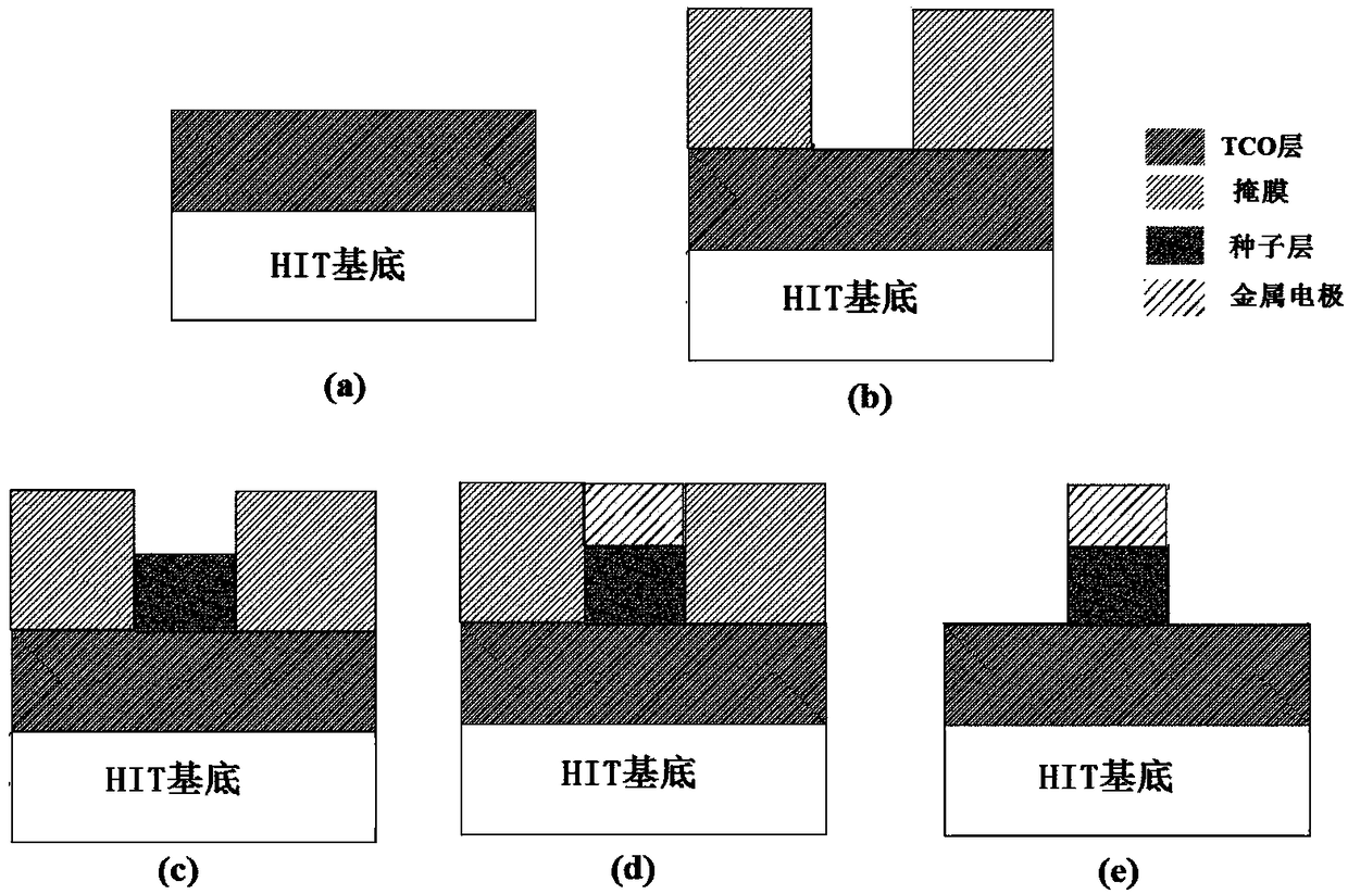
[0033] Such as figure 1 Shown, a kind of heterojunction solar cell preparation method with electroplated electrode comprises the following steps:

[0034] Step 1, preparing a transparent conductive thin film layer on the substrate of the heterojunction solar cell. The heterojunction solar cell substrate can add a transparent conductive thin film layer on the front or can add a transparent conductive thin film layer on the front and back of the heterojunction solar cell substrate. Here, adding a transparent conductive thin film layer on the front of the heterojunction solar cell substrate is Examples are explained in detail.

[0035] Step 2, forming a metal seed layer on a part of the transparent conductive film layer and forming a patterned mask on both sides of the metal seed layer. In the invention, a metal seed layer is firstly formed on a part of the transparent conductive film layer, and then a patterned mask is formed on both sides of the metal seed layer. Wherein, th...

specific Embodiment 2

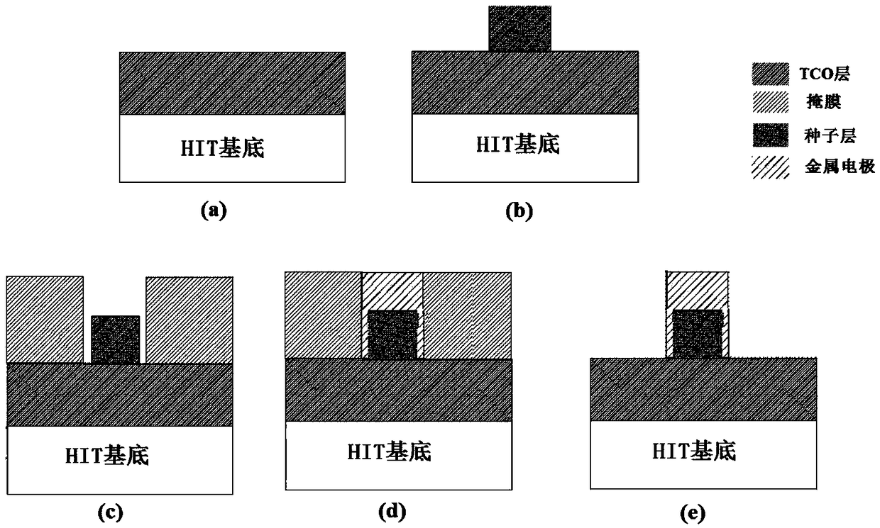
[0039] Such as figure 2 As shown, this embodiment is the same as the specific embodiment 1, except that in step 2, a patterned mask is first formed on both sides of the transparent conductive film layer, and then a metal seed layer is formed between the patterned masks.

specific Embodiment 3

[0040] Such as image 3 Shown, a kind of heterojunction solar cell preparation method with electroplated electrode comprises the following steps:

[0041] Step 1, preparing a transparent conductive thin film layer on the substrate of the heterojunction solar cell. The heterojunction solar cell substrate can add a transparent conductive thin film layer on the front or can add a transparent conductive thin film layer on the front and back of the heterojunction solar cell substrate. Here, adding a transparent conductive thin film layer on the front of the heterojunction solar cell substrate is Examples are explained in detail.

[0042] Step 2, forming a metal seed layer on a part of the transparent conductive film layer and forming a patterned mask on both sides of the metal seed layer. In the invention, a metal seed layer is firstly formed on a part of the transparent conductive film layer, and then a patterned mask is formed on both sides of the metal seed layer. Wherein, th...


PUM


Abstract

The invention discloses a preparation method of a heterojunction solar cell having an electroplated electrode. The preparation method comprises steps that S01, a transparent conductive thin film layeris prepared on the substrate of the heterojunction solar cell; S02, a metal seed layer is formed on a part of the transparent conductive thin film layer, and graphical masks are formed on the two sides of the metal seed layer; S03, metal is electroplated on an opening between the graphical masks; S04, the masks are removed. The invention also discloses the heterojunction solar cell having an electroplated electrode, which is prepared by adopting the above mentioned preparation method. The heterojunction solar cell having an electroplated electrode and the preparation method thereof are advantageous in that under a precondition of guaranteeing high absorption force between the electroplated metal and a TCO layer, the etching step of the seed layer is saved, and the etching on the TCO layer is prevented, and therefore the technological difficulty of the batch production of the solar cells is reduced, and liquid waste emission is reduced.

Description

technical field [0001] The invention specifically relates to a heterojunction solar cell with electroplating electrodes and a preparation method thereof, belonging to the field of heterojunction solar cells. Background technique [0002] With the depletion of traditional energy and the increasingly serious environmental pollution, photovoltaic power generation technology has attracted more and more attention and is considered as an important renewable and clean energy. It is the goal of the photovoltaic industry to improve the photoelectric conversion efficiency of photovoltaic cells, reduce the cost of power generation, and make it competitive with the cost of traditional grid power generation. [0003] Silicon heterojunction solar cell (HIT solar cell) is a kind of non-doped amorphous silicon film deposited on the front and rear surfaces of crystalline silicon wafers, and then P-type and N-type amorphous silicon films are deposited on the front and rear surfaces respective...

Claims


Application Information

Patent Timeline
IPC IPC(8): H01L31/0224H01L31/042H01L31/18
CPCH01L31/022425H01L31/042H01L31/1884Y02E10/50Y02P70/50
Inventor 李中天
Owner SUZHOU SUNWELL NEW ENERGY CO LTD
Why Eureka
Try Eureka