Tool for machining second-stage blade of free turbine of aero-engine

An aero-engine, free technology, applied in the direction of metal processing machinery parts, metal processing equipment, positioning devices, etc., can solve the problems of unqualified processing of the secondary blade 4, small diameter of the ball-end cutter, poor rigidity, etc., and achieve the clamping method Stabilization, reduced tool vibration, and improved machining efficiency

Pending Publication Date: 2018-08-17
CHINA HANGFA CHANGZHOU LANXIANG MACHINERY CO LTD
View PDF0 Cites 2 Cited by
  • Summary
  • Abstract
  • Description
  • Claims
  • Application Information

AI Technical Summary

Problems solved by technology

[0006] The above-mentioned method of processing the secondary blade 4 on the four-axis machining center has the following problems: when the tooling used in this processing method clamps the secondary blade 4, it is clamped in a way of clamping and topping, because the secondary blade 4 The structural shape of the surface to be processed is relatively thin, so the clamping method of one clamp and one top will cause the clamped blade 4 to receive a certain axial force and cause it to undergo elastic deformation. When the processing is completed and the tailstock is released After tipping, the internal stress on the secondary blade 4 disappears one after another. At this time, the shape of the processed blade surface produces rebound deformation and causes the processing of the secondary blade 4 to be unqualified. At the same time, the center hole used for clamping is the same A central hole, so there is a clamping error; the tool used for milling the surface to be processed of the secondary blade 4 is a D8r4 ball nose cutter, which has a small diameter and relatively poor rigidity, and at the same time due to the blade of the secondary blade 4 The machining allowance of each section of the body is inconsistent, so the cutting speed of the tool during milling is limited. The blade body of the blade 4 has no auxiliary support during milling, which further leads to serious tool vibration phenomenon, which leads to severe tool vibration phenomenon. The poor quality further limits the cutting speed of the cutting tool during processing; it takes about 5 hours to process a secondary blade 4, and the processing pass rate of the secondary blade 4 is about 30%, so the processing efficiency and processing quality of this processing method are both low. Can't achieve expected effect

Method used


Image

  • Tool for machining second-stage blade of free turbine of aero-engine
  • Tool for machining second-stage blade of free turbine of aero-engine
  • Tool for machining second-stage blade of free turbine of aero-engine

Examples


Embodiment Construction

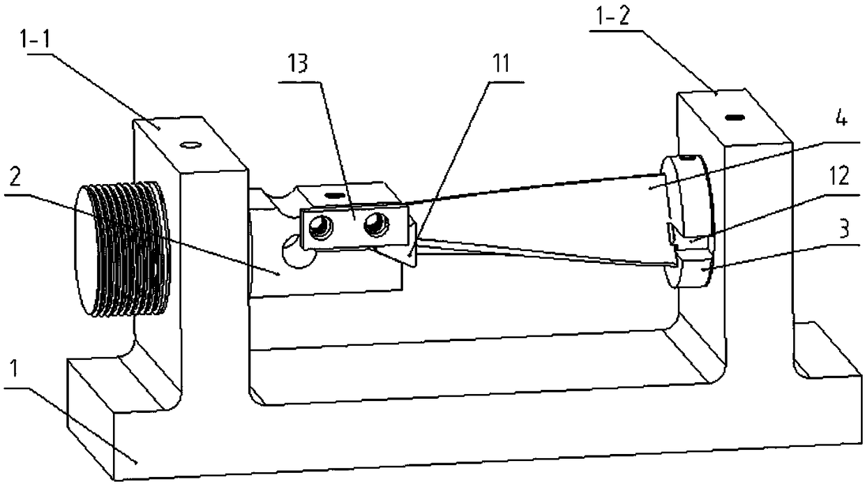
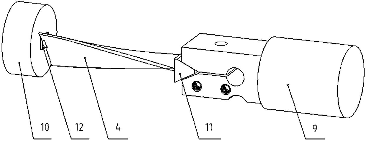
[0030] Such as figure 1 , a tooling for processing the second-stage blades of the free turbine of an aeroengine in this embodiment includes a base 1, and a vertical left support portion 1-1 and a right support portion 1 are provided on the left and right sides of the base 1 -2, a collet 2 is provided on the left supporting part, and a V-shaped tooth surface groove is provided on the right end surface of the collet 2;

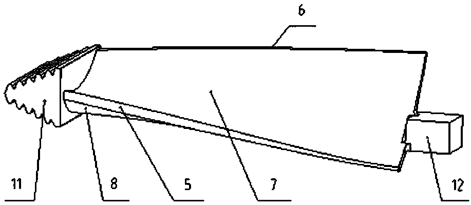
[0031] A top cover 3 is provided on the inner side of the right supporting part, and a rectangular groove is provided on the left end surface of the top cover 3. The workbench 12 at the right end of the secondary blade 4 is fixedly matched with the rectangular groove, and the V-shaped teeth The tenon 11 on the left end of the surface groove and the secondary blade 4 is fixedly matched.

[0032] The bottom surface of the base 1 is flat and is attached to the worktable of the three-axis machining center. The left and right ends of the bottom of the base 1 are pro...


PUM


Abstract

The invention relates to a tool for machining a second-stage blade of a free turbine of an aero-engine. The tool comprises a base, the left side and the right side of the base are provided with a vertical left supporting part and a vertical right supporting part respectively, a chuck is arranged on the left supporting part, and a V-shaped toothed surface groove is formed in the right end face of the chuck; a top sleeve is arranged on the inner side face of the right supporting part, and a rectangular groove is formed in the left end face of the top sleeve; and a workbench at the right end of the second-stage blade is fixedly matched with the rectangular groove, and the V-shaped toothed surface groove is fixedly matched with a tenon at the left end of the second-stage blade. By means of thetool, finish machining on to-be-machined surfaces of the secondary blade can be completed on a three-axis machining center, and dependence of an existing machining method on a four-axis machining center or manual machining is avoided; the efficiency of machining the secondary blade by using the tool is high, and time is saved; and on the premise of ensuring the qualified rate of the quality of the secondary blade, the machining quality of the to-be-machined surfaces of the secondary blade is uniform.

Description

technical field [0001] The invention relates to a tooling for aeronautical processing, in particular to a tooling for processing aeroengine free turbine secondary blades. Background technique [0002] The free turbine secondary blade 4 is an important part of an aero-engine, and its material is a forged superalloy GH93; the hardness is ≥ 290, and an engine needs to be equipped with more than 60 pieces of secondary blades 4, so the manufacturer's production demand for this part Larger; the surface to be processed of the secondary blade 4 includes a leading edge 5, a trailing edge 6, a leaf basin 7, and a blade back 8, the left end portion of the secondary blade is a tenon 11, and the right end portion of the secondary blade is a workbench 12. The secondary blade 4 before processing is rough processed by electric discharge machining, and the blade shape of the secondary blade 4 is processed by EDM, and a small machining allowance is left on each surface to be processed. After ...

Claims


Application Information

Patent Timeline
Patent Type & Authority Applications(China)
IPC IPC(8): B23Q3/06
CPCB23Q3/062
Inventor 彭正明周健刘壮李亮甲
Owner CHINA HANGFA CHANGZHOU LANXIANG MACHINERY CO LTD
Why Eureka
Try Eureka