Water floating wind driven generator built on vine pressure buoyancy raft

A technology of wind power generators and pressure, applied in the direction of wind power generators for storage of electricity, wind power generation, installation/support of wind power generators, etc., to achieve the effect of increasing market demand, increasing economic income, and avoiding large-scale water pollution

Inactive Publication Date: 2018-08-17
WUXI TONGCHUN NEW ENERGY TECH
View PDF4 Cites 2 Cited by
  • Summary
  • Abstract
  • Description
  • Claims
  • Application Information

AI Technical Summary

Problems solved by technology

At the same time, the electricity provided by floating wind farms has not been used to eliminate water pollution

Method used


Image

  • Water floating wind driven generator built on vine pressure buoyancy raft

Examples


Embodiment 1

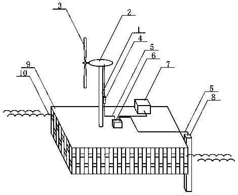
[0022] Install the wind power prop on the front of the upper surface of the rattan pressure floating raft, install the horizontal axis wind generator on the top surface of the wind power prop, install the blades on the front end of the horizontal axis wind generator, and install the wind power control on the side of the wind power prop device. On the rear of the upper surface of the rattan pressure raft, a micro-inverter and a liquid lithium-ion battery are installed. An electric water purifier is installed on the left wall surface of the rear side wall of the rattan pressure floating raft. The wind blows the blades to rotate and drives the horizontal axis wind turbine to generate current. The current output from the horizontal axis wind turbine is input into the wind power controller through the conductive wire, and the current is adjusted in the wind power controller. The current output from the wind power controller passes through the conductive wire. The wire is input int...

Embodiment 2

[0024]Install the wind power prop on the front of the upper surface of the rattan pressure floating raft, install the vertical axis wind turbine on the top surface of the wind power prop, install the blades on the front end of the vertical axis wind generator, and install the wind power control on the side of the wind power prop device. A micro-inverter and a solid-state lithium-ion battery are mounted on the rear of the upper surface of the rattan pressure raft. An electric water purifier is installed on the left wall surface of the rear side wall of the rattan pressure floating raft. The wind blows the blades to rotate and drives the vertical axis wind turbine to generate current. The current output from the vertical axis wind turbine is input into the wind power controller through the conductive wire, and the current is adjusted in the wind power controller. The current output from the wind power controller passes through the conductive wire. The wire is input into the mic...


PUM

PropertyMeasurementUnit
diameteraaaaaaaaaa

Abstract

The invention relates to a water floating wind driven generator built on a vine pressure buoyancy raft, and belongs to the technical field of environmental protection. A wind power support column anda wind driven generator are mounted at the front part of the upper surface of the vine pressure buoyancy raft; and a wind power controller is mounted on the side surface of the wind power support column. A micro inverter and an energy storage battery are mounted at the back part of the upper surface of the vine pressure buoyancy raft; and an electric water quality purifier is mounted on the left wall surface of the back side wall of the vine pressure buoyancy raft. Wind power blows blades to rotate to drive the wind driven generator to generate current; current output by the wind driven generator is input into the wind power controller through a lead; the current output from the wind power controller is input into the micro inverter through a lead; the current output from the micro inverter is input into the energy storage battery through a lead for storage of electric energy; the current output from the micro inverter is input into the electric water quality purifier through a lead; and electric power drives the electric water quality purifier to operate, so that sucked lake water flows through three layers of filter screens to remove pollutants in the lake water to improve the water quality.

Description

technical field [0001] The invention relates to a water floating wind power station assembled on rattan pressure floating rafts, and belongs to the field of new environmental protection technologies. Background technique [0002] Wind power is the conversion of wind kinetic energy into electrical energy. Wind power is a very environmentally friendly and pollution-free new energy source. China has abundant wind energy reserves both on land and on water. In 2017, China's wind power generation capacity reached 184.6 billion kWh. Due to the continuous improvement of wind power technology and the continuous decline in the cost of wind power generation, from 2010 to 2017, the cost of onshore wind power generation has been reduced by about a quarter. By 2020, the cost of electricity for onshore wind power projects can be reduced to parity Grid-connected electricity prices. The increase of wind power generation and the reduction of coal-fired power generation are conducive to red...

Claims


Application Information

Patent Timeline
Patent Type & Authority Applications(China)
IPC IPC(8): F03D13/20F03D9/11F03D9/32F03D80/00B63B35/44C02F1/00
CPCB63B35/44B63B2035/446C02F1/001F03D9/11F03D9/32F03D13/20F03D80/00Y02E10/72Y02E10/727Y02E10/728Y02E70/30
Inventor 林华
Owner WUXI TONGCHUN NEW ENERGY TECH
Why Eureka
Try Eureka