Pressure regulator of aircraft hydraulic brake system

A technology for pressure regulators and brake systems, applied in fluid pressure converters, mechanical equipment, brake actuators, etc., can solve problems such as unstable brake pressure, large operating force, and difficulty in debugging

Active Publication Date: 2018-08-17
XIAN AVIATION BRAKE TECH
View PDF11 Cites 5 Cited by
  • Summary
  • Abstract
  • Description
  • Claims
  • Application Information

AI Technical Summary

Problems solved by technology

The spring stiffness of the direct-acting pressure reducing valve is relatively large, so the outlet pressure of the valve changes slightly with the displacement of the valve core, that is, with the change of the flow rate flowing through the pressure reducing valve, and the output of the brake outlet is proportional to the braking pressure of the control force. Such a single-stage adjustment requires a large operating force. To obtain the braking pressure of the aircraft, the maximum operating force exceeds 1000N. The valve core has a high bearing force and a large strain, and it is difficult to ensure the clearance of the slide valve assembly.
The pressure regulator determines that the entire brake pressure is unstable, the pressure deflection is large, the hysteresis of the regulator is large, and it is difficult to debug during the production and assembly process
[0003] After retrieval of hydraulic pressure regulators (or pressure reducing valves) used in brake systems at home and abroad, there is no report on pilot-operated three-position three-way external force pressure regulators

Method used


Image

  • Pressure regulator of aircraft hydraulic brake system
  • Pressure regulator of aircraft hydraulic brake system
  • Pressure regulator of aircraft hydraulic brake system

Examples


Embodiment Construction

[0023] The specific embodiments of the present invention will be further described below in conjunction with the accompanying drawings.

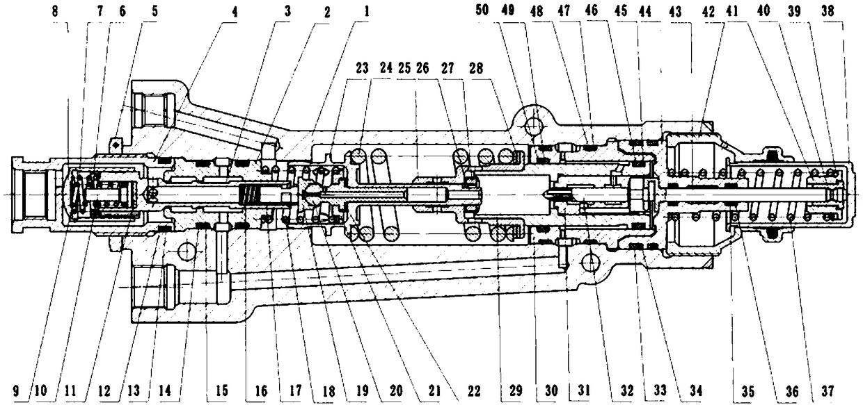
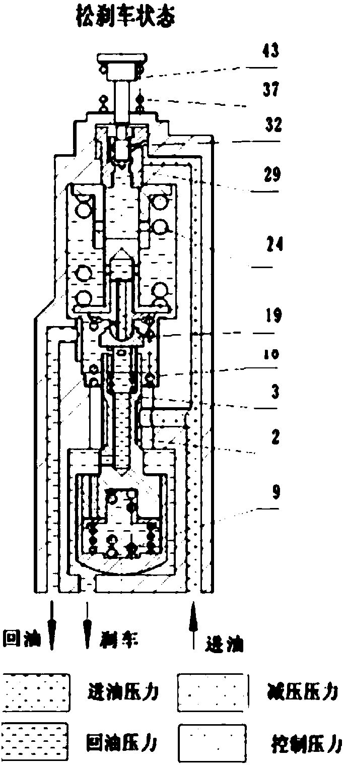
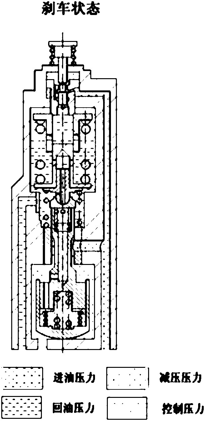
[0024] For the pressure regulation structure and principle diagram involved in the invention, see figure 1 ,figure 2, image 3 , The shell 1 is made of aluminum alloy LD5 die forging, and the shell is processed with M16×1.5, M12×1.5 threaded holes and 3-φ6.5 mounting holes for installing the oil inlet nozzle and the oil return nozzle.

[0025] One end of the inner cavity of the housing 1 is equipped with a bushing A2, which is fixed in the housing with a screw sleeve 4, and the screw sleeve is locked with a nut 5. A decompression diverter valve 3 is installed in the bushing. The outer circle of the decompression diverter valve is matched with the inner hole of the bushing, and the 90° conical surface is matched with the sharp edge of the end face of the inner hole of the bushing to isolate the oil inlet chamber. The role of working fluid w...


PUM


Abstract

The invention belongs to the technical field of aircraft brake system design, and relates to a pressure regulator of an aircraft hydraulic brake system. The pressure regulator comprises a shell (1), abush A (2), a pressure reducing and flow splitting valve (3), a spring B (16), a first sleeve (17), a fixing seat (20), a spring assembly, a piston assembly, a flow splitting control valve (32), a guide sleeve B (44), a piston rod (43) and a second sleeve (38). According to the pressure regulator, the control pressure comes from the outlet pressure, a main valve core is of an open type, a main valve is operated through the oil inlet pressure, the outlet pressure is introduced into a lower cavity of the main valve and then enters an upper cavity of the main valve through damping holes in the main valve core, the liquid discharging pressure of the main valve core and the operating force of an upper piston are balanced by the spring force, the operating force is applied to a pilot valve, oilliquid in an oil inlet enters an upper cavity of a piston of the main valve core and changes the pressure of the upper cavity of the piston of the main valve core, so that the outlet pressure is adjusted.

Description

technical field [0001] The invention belongs to the design technology of an aircraft brake system, and relates to a pressure regulator of an aircraft hydraulic brake system. Background technique [0002] The pressure regulator is the main accessory of the reliability and performance of the aircraft hydraulic brake system, and it should have sufficient sensitivity, vibration resistance, reliability and approximately linear static characteristics. The hydraulic brake system of the aircraft consists of a pressure regulator for hydraulic components, which outputs hydraulic brake pressure proportionally to brake the aircraft according to the control force and pedal stroke given by the pilot. The regulator is an essential hydraulic equipment for the aircraft brake system. , the traditional direct-acting pressure regulator is a three-position three-way valve. The valve has three states: loose brake, brake, and pressure holding. It is mainly composed of housing, slide valve assembly...

Claims


Application Information

Patent Timeline
Patent Type & Authority Applications(China)
IPC IPC(8): F16D65/14F15B3/00F16D121/02F16D125/02
CPCF15B3/00F16D65/14F16D2121/02F16D2125/02
Inventor 王衡张平高山
Owner XIAN AVIATION BRAKE TECH
Why Eureka
Try Eureka