Measurement platform for measuring time response characteristics of ultra-high speed camera

An ultra-high-speed camera and time-response technology, applied in the field of detection, can solve problems such as difficulty in maintaining consistent optical fiber output light intensity, insufficient measurement accuracy, and complex fiber bundle arrays, achieving comprehensive and accurate measurement results and simple measurement operations. Effect

Pending Publication Date: 2018-08-17
LASER FUSION RES CENT CHINA ACAD OF ENG PHYSICS
View PDF0 Cites 2 Cited by
  • Summary
  • Abstract
  • Description
  • Claims
  • Application Information

AI Technical Summary

Problems solved by technology

However, due to the larger the measurement range and the higher the accuracy, the fiber bundle array that needs to be fabricated is more complex and the cost is higher; moreover, in order to avoid the broadening of the laser pulse length by the fiber material, the fiber bundle array uses a single-mode fiber, and the coupling The efficiency is low, and the coupling efficiency is extremely sensitive to the incident angle of the laser. It is extremely difficult to keep the output light intensity of each fiber consistent in actual operation.
Therefore, when using this technology for camera testing, although the total exposure time of the camera can be given, due to the large difference in the output light intensity of each optical fiber, the opening / closing time of the camera cannot be accurately given from the intensity change of each optical fiber. and the response curve during the exposure
In another technical solution that uses a pulsed laser to measure the key component that controls the shutter exposure time in a high-speed camera-MCP image intensifier-on / off time characteristics, a laser with a pulse width of hundreds of picoseconds is used, resulting in measurement accuracy Seriously insufficient, it is not suitable for the measurement of time response characteristics of ultra-high-speed cameras with exposure times as fast as sub-nanoseconds, and due to the lack of real-time monitoring of laser output energy, the response curve of the camera during the exposure process cannot be accurately given

Method used


Image

  • Measurement platform for measuring time response characteristics of ultra-high speed camera
  • Measurement platform for measuring time response characteristics of ultra-high speed camera
  • Measurement platform for measuring time response characteristics of ultra-high speed camera

Examples


Embodiment Construction

[0035] The present invention will be further described below in conjunction with accompanying drawing description and embodiment, and the mode of the present invention includes but not limited to following embodiment.

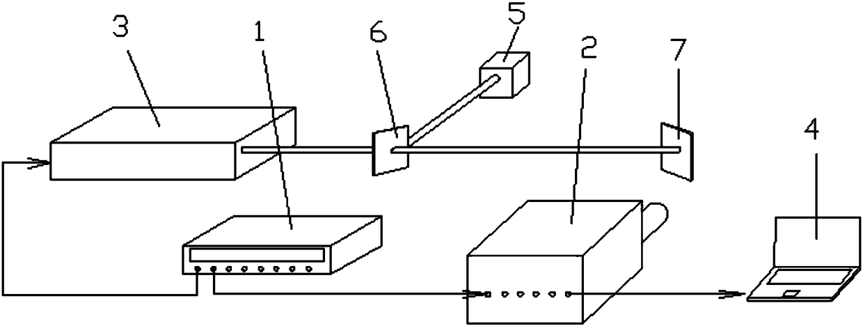
[0036] This embodiment provides an ultra-high-speed camera time response measurement platform, such as figure 1 As shown, the measurement platform includes Stanford Research Systems DG645 or higher-precision synchronous machine 1, ultra-high-speed camera 2, ultrashort pulse laser 3, PC 4, energy card meter 5, beam splitter 6 and diffuse reflection screen 7 .

[0037] Wherein, the high-precision synchronous machine 1 is provided with two output terminals, one output terminal is opposite to the ultrashort pulse laser, and is used to trigger the ultrashort pulse laser 3 so that the ultrashort pulse laser 3 outputs a single pulse laser beam, and the other The output end is opposite to the ultra-high-speed camera 2 to trigger the ultra-high-speed camera 2; the beam...


PUM

PropertyMeasurementUnit
Wavelengthaaaaaaaaaa
Thicknessaaaaaaaaaa

Abstract

The invention discloses a measurement platform for measuring time response characteristics of an ultra-high speed camera. The platform includes an ultra-short pulse laser, a high precision synchronousmachine, a beam splitter, an energy calorimeter and a diffuse reflection screen. Moreover, a method for measuring time response characteristics of an ultra-high speed camera by using the platform isprovided. The method includes the steps of controlling the ultra-short pulse laser to output a single-pulse laser beam through the high precision synchronous machine, and monitoring the output energyof each laser by using the energy calorimeter and the beam splitter; a laser beam passing through the beam splitter being incident on the diffuse reflection screen to form uniformly scattered spots; and while the beam reaches the diffuse reflection screen, the high precision synchronous machine triggering the ultra-high speed camera to control the ultra-high speed camera to photograph the scattered spots on the screen and obtain an image with an intensity response. The time response characteristics of the ultra-high speed camera can be obtained through a series of normalization processes. Compared with the prior art, the measurement platform and the method have the advantages of simple structure, more comprehensive and accurate measurement results and low cost.

Description

technical field [0001] The invention relates to the technical field of detection, in particular to an ultra-high-speed camera time response characteristic measurement platform and measurement method. Background technique [0002] Ultra-high-speed cameras have important application value in many research fields such as shock wave physics, detonation physics, plasma physics, accelerator physics, high-voltage discharge, and combustion. Generally, the exposure time of an ultra-high-speed camera can be as fast as sub-nanoseconds, and the exposure time is adjustable, so it can be used for ultra-high-speed photography of various rapidly changing physical processes. In the actual application process, the measurement of the time response characteristics of the ultra-high-speed camera, including the opening / closing time of the whole exposure process, the total exposure time and the response curve during the exposure process, is the basis for checking the working state of the camera, a...

Claims


Application Information

Patent Timeline
IPC IPC(8): G01M11/00
CPCG01M11/00
Inventor 朱斌滕建吴玉迟谷渝秋税敏范伟董克攻谭放于明海张天奎闫永宏李纲卢峰杨月
Owner LASER FUSION RES CENT CHINA ACAD OF ENG PHYSICS
Why Eureka
Try Eureka