
All-fiber high-order mode Brillouin fiber laser

A fiber laser, high-order mode technology, applied in lasers, laser parts, phonon exciters, etc., can solve the problems of beam power and quality degradation, low purity of output high-order mode modes, etc., to achieve easy promotion and use, improve practicability and reliability. performance, low cost

Pending Publication Date: 2018-08-17
SOUTH CHINA UNIV OF TECH
View PDF5 Cites 1 Cited by
  • Summary
  • Abstract
  • Description
  • Claims
  • Application Information

AI Technical Summary

Problems solved by technology

In addition, due to the imperfection of the device, these two layouts will also lead to degradation of beam power and quality, and the output high-order modes have low purity

Method used


Image

  • All-fiber high-order mode Brillouin fiber laser
  • All-fiber high-order mode Brillouin fiber laser
  • All-fiber high-order mode Brillouin fiber laser

Examples


Embodiment 1

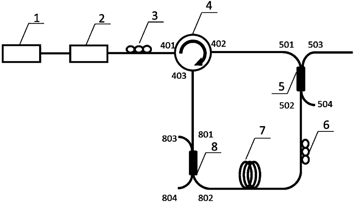
[0025] like figure 1 As shown, an all-fiber high-order mode Brillouin fiber laser of this example includes: a narrow linewidth pump laser 1, an optical amplifier 2, a first polarization controller 3, a fiber circulator 4, and a first fiber mode selective coupler 5. The second polarization controller 6 , the few-mode fiber 7 and the second fiber mode selective coupler 8 .

[0026] The laser output by the narrow linewidth pump laser 1 is power amplified by the amplifier 2, and the amplified high-power pump light is injected into the first port 401 of the fiber circulator 4, and then injected into the first port 402 from the second port 402 of the fiber circulator 4. The first port 501 of the fiber mode selective coupler 5, after passing through the first fiber mode selective coupler 5, the pump light is converted from the fundamental transverse mode of the single-mode fiber in the first port 501 to the first fiber mode selective coupler 5. The pump light of the specific high-or...

Embodiment 2

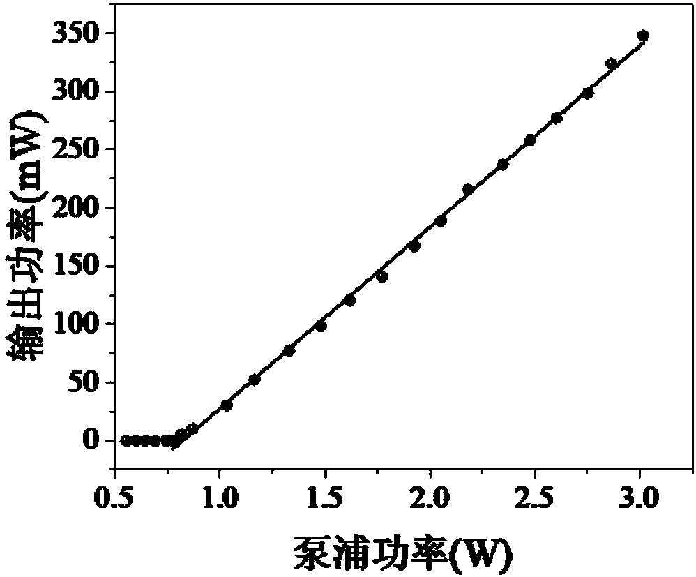
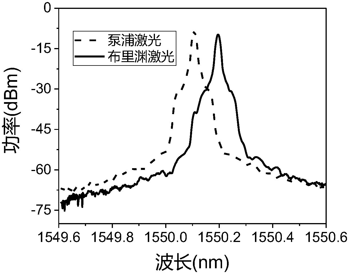
[0034] An all-fiber high-order mode Brillouin fiber laser, the schematic diagram is as follows figure 1shown. The narrow-linewidth pump laser 1 uses a 1550nm-band narrow-linewidth single-frequency fiber laser with a linewidth of 10kHz and a laser power of 30mW. Optical amplifier 2 adopts commercial 1550nm band semiconductor optical amplifier, and the amplification power can reach 5W. The optical fiber circulator 4 adopts a commercial three-port single-mode optical fiber circulator. The first fiber mode selective coupler 5 and the second fiber mode selective coupler 8 are both 2×2 couplers made of ordinary communication single-mode fiber SMF-28e and commercial two-mode step fiber fused taper, single-mode fiber The conversion efficiency of the LP01 mode in the two-mode step fiber to the LP11 mode in the fiber is 90%. The single-mode fibers in the optical path are all SMF-28e fibers. The length of the two-mode step fiber in the ring cavity is 50m, and the length of the single...


PUM

PropertyMeasurementUnit
Widthaaaaaaaaaa
Lengthaaaaaaaaaa
Lengthaaaaaaaaaa

Abstract

The invention discloses an all-fiber high-order mode Brillouin fiber laser with a ring cavity structure. The all-fiber high-order mode Brillouin fiber laser includes a narrow linewidth pump laser, anoptical amplifier, a first polarization controller, a fiber circulator, a first fiber mode selective coupler, a second polarization controller, a single-mode fiber, a few-mode fiber, and a second fiber mode selective coupler. The first fiber mode selective coupler and the second fiber mode selective coupler are intracavity mode conversion devices. The directional selective coupling of a fundamental transverse mode in the single-mode fiber and a specific high-order mode in the few-mode fiber can be implemented. On the basis of the Brillouin nonlinear gain of the small-mode fiber in the ring cavity, the resonant amplification of the high-order mode in the cavity is realized, and the high-order mode laser can be directly output. The output high-order mode laser of the invention has good stability and high mode purity. The all-fiber high-order mode Brillouin fiber laser adopts the all-fiber structure and is compact in structure, low in cost, and easy to integrate with a fiber system, and the practicability and reliability of the high-order mode laser are improved.

Description

technical field [0001] The invention relates to the fields of fiber lasers and optical communications, in particular to an all-fiber high-order mode Brillouin fiber laser. Background technique [0002] Due to their unique spatial intensity, phase, and polarization distributions, higher-order mode lasers have broad application prospects and have attracted increasing interest. For example, in the field of optical communication, information is modulated on several different higher-order modes, that is, mode division multiplexing technology, which can significantly improve the transmission capacity in optical communication. In the field of optical fiber sensing, higher order modes can achieve higher temperature and strain resolution accuracy. In addition, vortex lasers derived from higher-order modes have great potential in quantum and nano-optics, optical manipulation, super-resolution imaging, and laser material processing. [0003] Driven by these applications, researchers ...

Claims


Application Information

Patent Timeline
IPC IPC(8): H01S3/067H01S3/094H01S3/30
CPCH01S3/06712H01S3/06716H01S3/06754H01S3/06791H01S3/094H01S3/094042H01S3/302Y02A90/10
Inventor 甘久林衡小波杨中民张智深
Owner SOUTH CHINA UNIV OF TECH
Learn More