
Self generating assembly applicable to rolling bearing test system

A test system and rolling bearing technology, applied in the direction of electrical components, circuit devices, etc., can solve problems such as difficult integration, complex environment, large size, etc., and achieve the effect of reliable energy self-supply

Inactive Publication Date: 2018-08-21
XI AN JIAOTONG UNIV
View PDF8 Cites 0 Cited by
  • Summary
  • Abstract
  • Description
  • Claims
  • Application Information

AI Technical Summary

Problems solved by technology

The main reason is that the bearing is installed in the bearing seat, the space is narrow and the environment is complicated
The relatively mature generator structure can realize energy self-supply, but the generator structure is complicated and the volume is large, so it is difficult to integrate into the shafting assembly of the bearing
Ding Chuang and Zhao Yongdong from the Mechanical Engineering Department of Armored Corps Engineering College used electromagnetic coupling wireless power supply technology to realize torque measurement through non-contact inductive power supply technology. supply, and the primary coil used in the power supply process must use an external power supply, so as to realize wireless power supply, and for a static test system, a separate power supply unit needs to be added
Ren Zongjin, Zhang Jun and others from Dalian University of Technology proposed the scheme in the patent "An Experiment for Respectively Realizing the Rotation of the Inner and Outer Rings of a Power Generation Device" which can realize two forms of motion in which the inner and outer rings rotate separately, and achieve the principle test and test of the power generation device. For the purpose of engineering simulation test, the structure is simple, and the inner and outer rings are rotated separately through the one-way bearing, but the installation space of the rolling bearing is extremely limited, so it is difficult to integrate this solution into the inner and outer ring test system of the bearing
Shi Gengchen, Sui Li and others from Beijing Institute of Technology patented the axial magnetic field magnetoelectric micro-generator to use wind energy to realize the relative motion of the stator and rotor in the generator to generate electric energy. However, this structure only realizes the rotating coil to generate electricity. Leading out electrical energy, due to the existence of mechanical components such as balls, makes the structure size large, it is difficult to integrate into the narrow installation space of the bearing, and it does not realize the synchronous energy supply to the bearing stationary component test system and the rotating component test system
The photoelectric conversion energy supply can realize the energy supply to the rotating parts test system. It drives the energy receiving end through strong light irradiation, and then converts the light energy into electrical energy to meet the energy demand of the system. However, for the working environment of the bearing, this energy supply The solution is difficult to deal with, the environment with oil and oil mist can easily block the transmission of light, and the deposition of oil on the energy receiving end is inevitable, and the structure is complex, which is difficult to apply to the actual working conditions of rolling bearings.

Method used


Image

  • Self generating assembly applicable to rolling bearing test system
  • Self generating assembly applicable to rolling bearing test system
  • Self generating assembly applicable to rolling bearing test system

Examples


Embodiment Construction

[0019] The specific implementation process of the present invention will be further explained below in conjunction with the accompanying drawings.

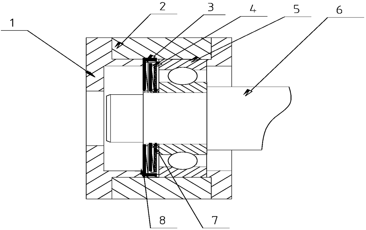
[0020] A self-generating component suitable for rolling bearing testing systems, mainly driven by the power of the rotating shaft system to rotate the moving ring to realize the relative movement between the moving ring and the static ring, and then use the principle of electromagnetic induction to generate a certain amount of electric energy for use in the testing system.

[0021] refer to figure 1 , figure 1 Among them, 1 is the bearing end cover, 2 is the bearing seat, 3 is the static ring installed to the outer ring of the bearing, 4 is the moving ring installed to the inner ring of the bearing, 5 is the bearing, and 6 is the shaft. A self-generating component suitable for a rolling bearing test system, installed in the working space of the bearing 5, including a moving ring 4 and a static ring 3 arranged concentrically and a...


PUM


Abstract

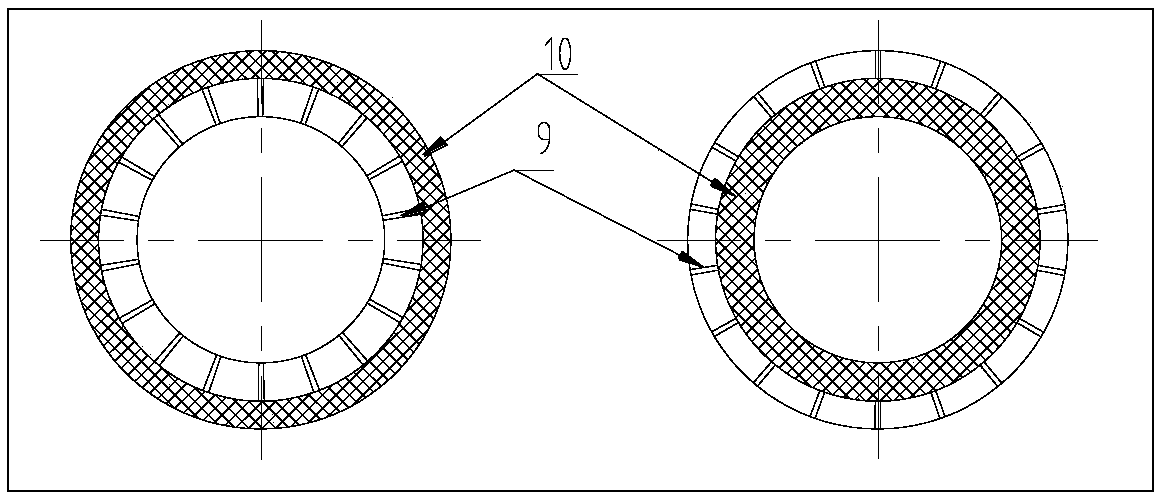
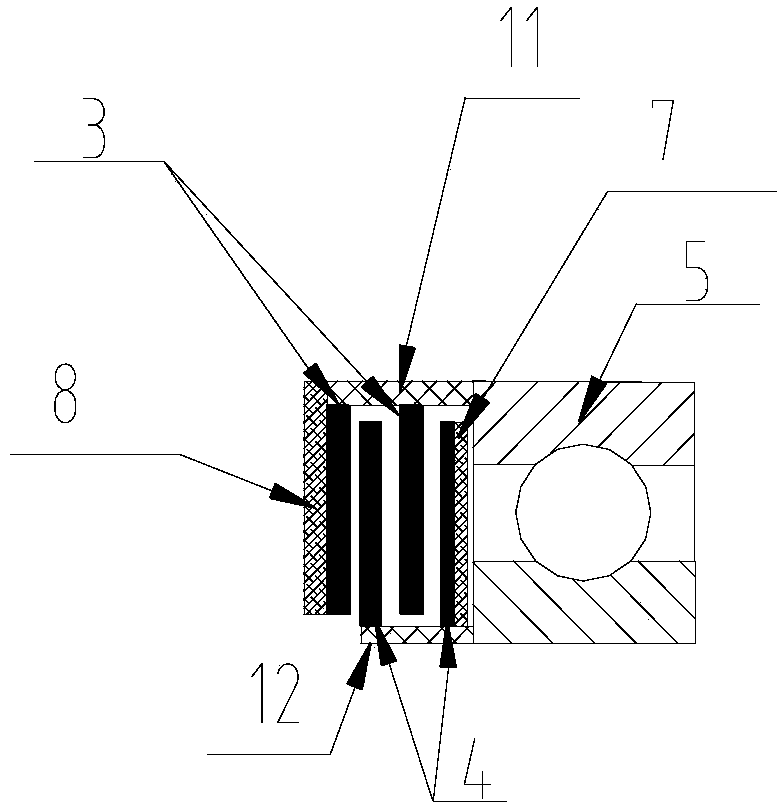
The invention discloses a self generating assembly applicable to a rolling bearing test system, which is mounted in bearing working space and comprises moving rings and stationary rings concentricallyand axially arranged. The stationary rings are arranged at the outer ring of the bearing, and the moving rings are arranged at the inner ring of the bearing; guide bars and magnetic grids are arranged at the inner ring and the outer ring of the stationary rings; positions, relative to the guide bars and the magnetic grids of the stationary rings, at the inner ring and the outer ring of the movingrings are also provided with magnetic grids and guide bars; in a condition in need of higher electric energy or higher magnetic field strength, at least two sets of stationary rings and moving ringsare adopted for mutual stagger arrangement; and in a condition in need of AC power supply, two poles of the magnetic grids are distributed at intervals. As the magnetic grids and the guide bars are arranged on the stationary rings and the moving rings, electric energy is generated through relative movement of the stationary rings and the moving rings, an integrated electric energy conditioning system is matched, and in narrow bearing serving space, self supply of energy for a stationary component test system and a rotating parts test system can be realized at the same time.

Description

technical field [0001] The invention relates to the field of dynamic monitoring of the health status of key components of mechanical equipment, in particular to a self-generating component suitable for a rolling bearing testing system. Background technique [0002] Rolling bearings are widely used in important fields such as aerospace, railways, ships, and large machine tools. As a key component of rotating machinery, rolling bearings play an important role in supporting shafting and transmitting power. At the same time, rolling bearings are also the weakest link in rotating machinery. According to statistics, 30% of the failures of rotating machinery are caused by bearing damage. Therefore, whether the rolling bearings are in normal operation often directly affects the performance of the entire equipment. For this reason, long-term condition monitoring of bearings is extremely important. The intelligentization of bearings, that is, the integration of data acquisition and c...

Claims


Application Information

Patent Timeline
Patent Type & Authority Applications(China)
IPC IPC(8): H02J50/10
CPCH02J50/10
Inventor 朱永生闫柯王方哲王宪陈东张进华洪军
Owner XI AN JIAOTONG UNIV
Learn More