Carrier for sheet wafer processing

A flake crystal and carrier technology, used in manufacturing tools, metal processing equipment, stone processing equipment, etc., can solve problems such as increased processing costs, fragmentation of functional wafers, unfavorable production and operation, and improved processing accuracy and efficiency. The effect of improving and avoiding additional labor intensity

Active Publication Date: 2018-08-24
抚州市东乡区东红光学科技有限公司
View PDF6 Cites 6 Cited by
  • Summary
  • Abstract
  • Description
  • Claims
  • Application Information

AI Technical Summary

Problems solved by technology

[0003] And in the prior art, in order to facilitate the separation of the functional wafer and the carrier wafer, and also to reduce the processing cost, the above-mentioned carrier wafer is mostly made of engineering plastics, and the carrier wafer made of this engineering plastic The circle is cut synchronously with the cutting process of the functional wafer, so the carrier wafer made of this engineering plastic in the prior art is mostly a disposable consumable
[0004] However, in the prior art, the functional wafer and the temporarily bonded product of the carrier wafer are clamped by the conventional mechanical angle on the processing machine tool, which can easily cause the functional wafer to break, so the processing is difficult.
The selection of engineering plastics with better strength and hardness will lead to an increase in processing costs, which is not conducive to the production and operation of enterprises.

Method used


Image

  • Carrier for sheet wafer processing
  • Carrier for sheet wafer processing
  • Carrier for sheet wafer processing

Examples


Embodiment 1

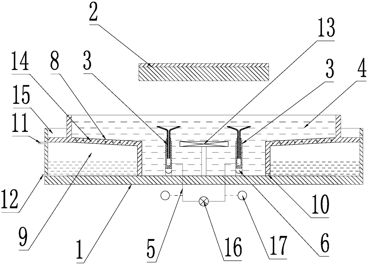
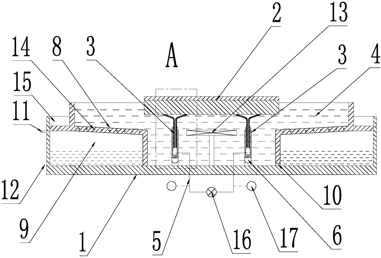
[0026] The invention provides a carrier for sheet wafer processing, which includes such as figure 1 The housing 1 shown with the opening direction upwards is provided with an adjustment mechanism 3 for adjusting the horizontal inclination of the product 2 inside the housing 1, and the magneto-rheological fluid 4 is poured into the housing 1, so that the adjustment mechanism 3 Immersed in the magnetorheological fluid 4, when the lower part of the product 2 is connected to the adjustment mechanism 3, the adjustment mechanism 3 drives the product 2 to swing to the set position and then rests, and the part to be processed of the product 2 is located in the magnetic flow Above the liquid level of the variable fluid 4 , the housing 1 is provided with a magnetic field generator for driving the magnetorheological fluid 4 in the housing 1 to solidify or return to a fluid state.

[0027] The above-mentioned setting position refers to the position of the product to be processed on the ma...

Embodiment 2

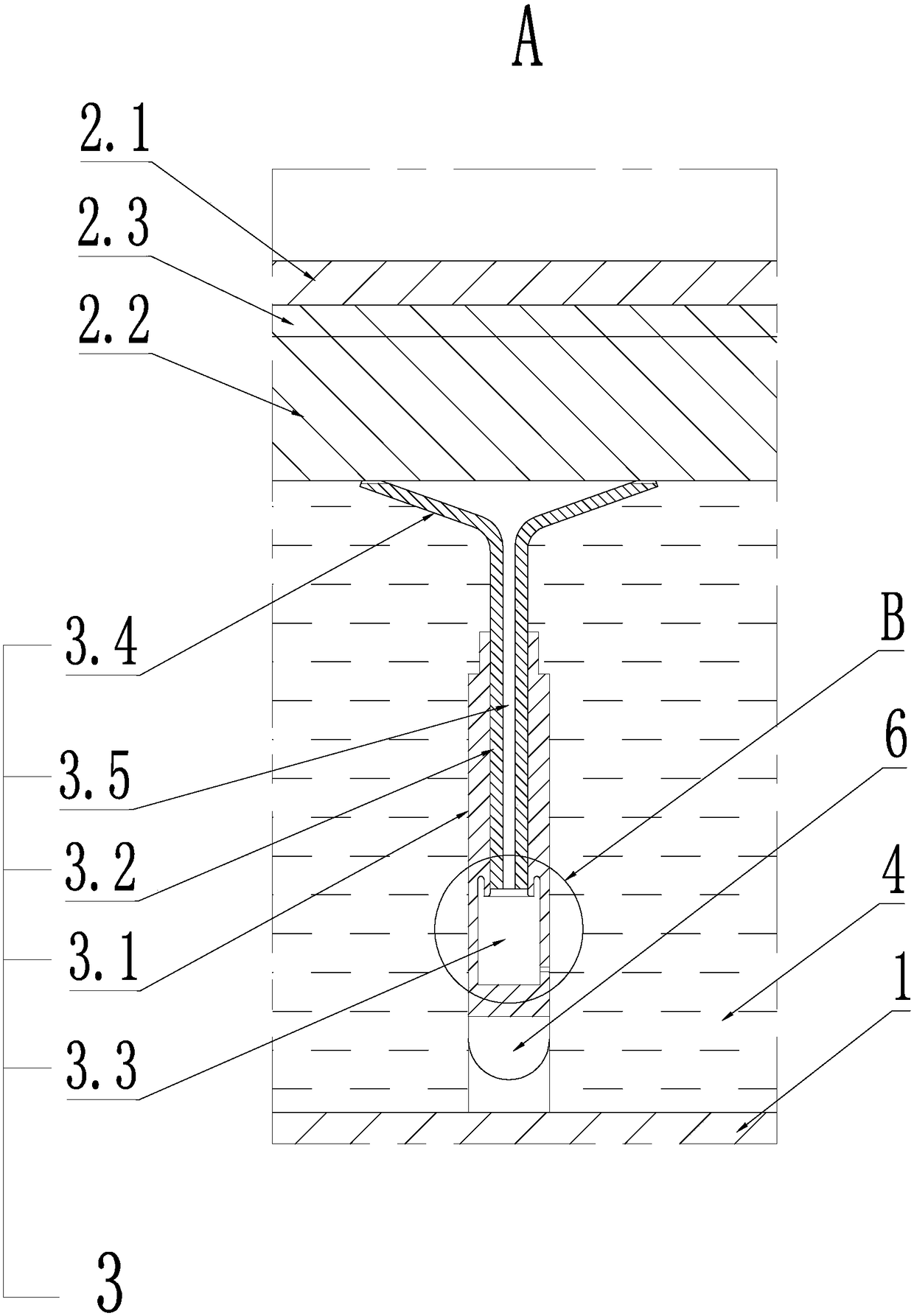
[0031] The general structure is the same as that of Embodiment 1, the difference is that: the adjustment mechanism 3 includes at least three cylinders 3.1, specifically preferably four cylinders 3.1, all cylinders 3.1 are arranged at intervals along the horizontal direction, and each cylinder 3.1 The lower ends are all connected to the housing 1, and a central channel is provided in the cylinder body 3.1, and a piston rod 3.2 is slidably fitted in the central channel, and the lower end surface of the piston rod 3.2 is surrounded by the inner surface of the central channel to form a control chamber 3.3, and the piston rod 3.2 The upper end of the piston rod 3.2 is exposed above the cylinder body 3.1 in the vertical direction, and the end of the piston rod 3.2 exposed above the cylinder body 3.1 is provided with a connecting piece for connecting or disconnecting the product 2.

[0032]The general structure is the same as that of Embodiment 1, the difference is that the adjustment...

Embodiment 3

[0036] The general structure is the same as that of the second embodiment, except that the connecting piece is a suction cup 3.4 with the opening facing upward.


PUM


Abstract

The invention discloses a carrier for sheet wafer processing. The carrier comprises a shell with an upward opening, and adjusting mechanisms used for adjusting the horizontal inclination angle of a product is arranged in the shell; magnetorheological fluid is poured into the shell, so that the adjusting mechanisms are immersed in the magnetorheological fluid, and when the lower part of the productis connected to the adjusting mechanisms, the adjusting mechanisms drive the product to swing to a set position for standing, and a to-be-processed part of the product is located above the magnetorheological fluid level; and a magnetic field generator is arranged on the shell and is used for driving the magnetorheological fluid in the shell to be solidified or reset to be in a fluid state. According to the carrier for sheet wafer processing, the performance requirement of the slide wafer is low, so that the consumable cost is low, meanwhile, the fragment rate of the functional wafer is low onthe basis of firm clamping, and the qualified rate of the whole product is high.

Description

technical field [0001] The invention relates to the technical field of wafer processing, in particular to a carrier for sheet wafer processing. Background technique [0002] Sheet wafers, especially thin wafers with a thickness of less than 1 mm, often need to be temporarily bonded to a carrier wafer during processing, so as to improve the strength of the functional wafer and facilitate processing. For example, thinning and grinding, etching, cutting, etc., and finally the functional wafer is separated from the carrier wafer to complete the processing of the functional wafer. [0003] And in the prior art, in order to facilitate the separation of the functional wafer and the carrier wafer, and also to reduce the processing cost, the above-mentioned carrier wafer is mostly made of engineering plastics, and the carrier wafer made of this engineering plastic The circle is cut synchronously with the cutting process of the functional wafer, so the carrier wafer made of this engi...

Claims


Application Information

Patent Timeline
Patent Type & Authority Applications(China)
IPC IPC(8): B24B19/22B24B41/06B28D5/00
CPCB24B19/22B24B41/06B28D5/0088
Inventor 韩赛
Owner 抚州市东乡区东红光学科技有限公司
Why Eureka
Try Eureka