
Oil drilling and exploitation well cementation slurry mixing device

A drilling and cementing and cementing technology, which is applied in the direction of cement mixing device, control device, clay preparation device, etc., can solve the problems of high labor intensity, poor mixing effect, inconvenient use, etc., so as to improve the mixing effect, Avoid precipitation, fully stir the effect

Inactive Publication Date: 2018-08-24
成都迪万斯科技有限公司
View PDF0 Cites 4 Cited by
  • Summary
  • Abstract
  • Description
  • Claims
  • Application Information

AI Technical Summary

Problems solved by technology

[0003] Most of the existing slurry mixing devices use the motor to drive the stirring shaft to rotate for stirring, but this stirring method makes the cement slurry rotate in one direction, which is prone to sedimentation, and has a certain centrifugal force, which makes the external admixture and admixture It will be separated under the action of centrifugal force, so that the mixing effect is not good, the mud is uneven, and the existing mixing device is labor-intensive when feeding, which is inconvenient to use

Method used


Image

  • Oil drilling and exploitation well cementation slurry mixing device
  • Oil drilling and exploitation well cementation slurry mixing device
  • Oil drilling and exploitation well cementation slurry mixing device

Examples


Embodiment Construction

[0016] The following will clearly and completely describe the technical solutions in the embodiments of the present invention with reference to the accompanying drawings in the embodiments of the present invention. Obviously, the described embodiments are only some, not all, embodiments of the present invention.

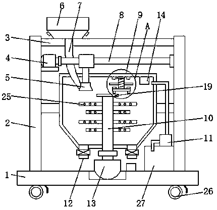
[0017] refer to Figure 1-3 , a cement mixing device for oil drilling and production, comprising a base 1, the lower end of the base 1 is symmetrically provided with rollers 26 on both sides, and the lower end of the base 1 is symmetrically provided with locking pieces matching the rollers 26, and the rollers 26 can be It is convenient to move the device, and the locking member can lock the roller 26 when it does not need to be moved, so as to enhance the stability.

[0018] The upper end of the base 1 is symmetrically provided with support rods 2 on both sides, the upper end of the support rods 2 is connected to the top plate 3, a crossbeam is arranged between the t...


PUM


Abstract

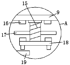
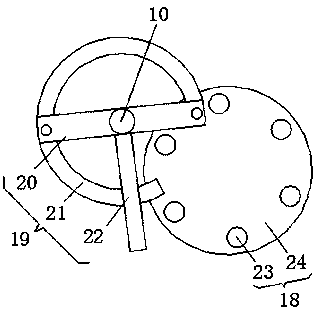
The invention relates to the technical field of oil drilling and exploitation well cementation, in particular to an oil drilling and exploitation well cementation slurry mixing device. The slurry mixing device comprises a base; a storage hopper is arranged on one side of the upper end of a top plate; a first motor is arranged on one side of the upper portions of supporting rods; an output shaft ofthe first motor is connected with a lead screw; a second motor is arranged in the middle of the upper end of the base; an output shaft of the second motor penetrates through a stirring bin to be connected with a stirring frame; a driving device is fixedly connected to the upper end of the stirring frame; a threaded rod is connected to one side of the upper end of the stirring bin in a rotating mode; a driven device is connected to the lower end of the threaded rod; and pressure sensors matched with a contact plate are arranged on the two sides of the threaded rod and the two sides of the upper end of a turntable separately. The slurry mixing device has the advantages of being reasonable in structural design and convenient to use, a cement mixture can be alternately stirred clockwise and anticlockwise through the stirring frame, and therefore slurry can be prevented from being precipitated, and meanwhile, the cement mixture can be sufficiently stirred.

Description

technical field [0001] The invention relates to the technical field of oil drilling and cementing, in particular to a cement slurry mixing device for oil drilling and cementing. Background technique [0002] In oil field construction operations, in order to strengthen the well wall, ensure continuous drilling, seal oil layers, gas and water layers, ensure layered oil testing during exploration and reasonable oil and gas production in the entire production, high-quality steel pipes are lowered for this purpose, and The operation of filling cement slurry between the wellbore and the steel pipe is called cementing operation. Cementing cement slurry is made by mixing oil well cement, external admixtures, admixtures and a certain proportion of construction water. [0003] Most of the existing slurry mixing devices use the motor to drive the stirring shaft to rotate for stirring, but this stirring method makes the cement slurry rotate in one direction, which is prone to sedimenta...

Claims


Application Information

Patent Timeline
Patent Type & Authority Applications(China)
IPC IPC(8): B28C5/16B28C5/08B28C7/12B28C7/02B28C7/06
CPCB28C5/16B28C5/0806B28C5/0856B28C7/02B28C7/067B28C7/126
Inventor 李丹
Owner 成都迪万斯科技有限公司
Learn More