Inflatable thin film method for preparing micro-nano structure of flexible thin film substrate

A technology of micro-nano structure and flexible film, which is applied in the manufacture of nano-structures, the formation of specific nano-structures, the manufacture of micro-structure devices, etc., can solve the problem that the flexible film substrate and the reticle are not tightly attached and cannot meet the high-precision requirements of micro-nano devices and other problems, to achieve the effect of high process repeatability and reliability, high consistency, and batch preparation

Inactive Publication Date: 2018-08-24
INST OF OPTICS & ELECTRONICS - CHINESE ACAD OF SCI
View PDF5 Cites 5 Cited by
  • Summary
  • Abstract
  • Description
  • Claims
  • Application Information

AI Technical Summary

Problems solved by technology

[0003] However, in the process of contact exposure, due to the existence of problems such as the flexible film substrate and the mask are not tightly bonded, the micro-nano structure of the flexible film substrate prepared by the prior art method has non-negligible line width error and depth error, which cannot meet High-precision requirements for micro-nano devices in scientific research and industry

Method used


Image

  • Inflatable thin film method for preparing micro-nano structure of flexible thin film substrate

Examples


Embodiment 1

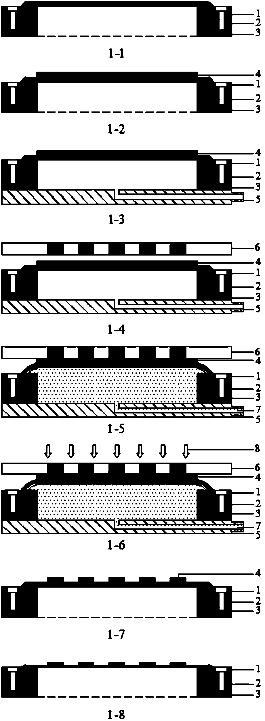
[0028] Such as figure 1 As shown in middle 1-1, the flexible film substrate 2 is fixed by two aluminum fixtures, the upper fixture 1 and the lower fixture 3, wherein the flexible film substrate 2 is a polyimide film substrate;

[0029] Such as figure 1 As shown in 1-2, AZ1500 photoresist 4 with a thickness of 600nm is evenly coated on the upper surface of the polyimide film substrate, and baked on a hot plate at 100°C for 60 seconds;

[0030] Such as figure 1 As shown in middle 1-3, fix the aluminum backboard 5 with air-filled holes on the lower fixture 3;

[0031] Such as figure 1 As shown in 1-4, take a traditional hard mask plate 6 and install it on the mask holder of the contact exposure machine, and use the lifting system of the contact exposure machine to adjust the gap between the mask plate 6 and the photoresist 4 as 40um;

[0032] Such as figure 1 As shown in 1-5, a certain volume of air 7 is filled into the sealed cavity through the air hole, and under the effe...

Embodiment 2

[0037] Such as figure 1 As shown in middle 1-1, the flexible film substrate 2 is fixed by two aluminum fixtures, the upper fixture 1 and the lower fixture 3, wherein the flexible film substrate 2 is a polyethersulfone film substrate;

[0038] Such as figure 1 As shown in 1-2, AZ3100 photoresist 4 with a thickness of 1.2um is evenly coated on the upper surface of the polyethersulfone film substrate, and baked on a hot plate at 100°C for 150 seconds;

[0039] Such as figure 1 As shown in middle 1-3, fix the aluminum backboard 5 with air-filled holes on the lower fixture 3;

[0040] Such as figure 1 As shown in 1-4, take a traditional hard mask plate 6 and install it on the mask holder of the contact exposure machine, and use the lifting system of the contact exposure machine to adjust the gap between the mask plate 6 and the photoresist 4 as 20um;

[0041] Such as figure 1 As shown in 1-5, a certain volume of air 7 is filled into the sealed cavity through the air hole, and...


PUM


Abstract

The invention discloses an inflatable thin film method for preparing a micro-nano structure of a flexible thin film substrate. The method comprises the following steps: firstly, clamping the flexiblethin film substrate with an upper clamp and a lower clamp; then fixing a back plate with an inflating hole below the lower clamp; and in a contact exposure process, seamlessly and tightly fitting theflexible thin film substrate and photoresist on the surface of the flexible thin film substrate with a mask plate by using fed gas, so as to obtain the high-precision micro-nano structure. Compared with an existing technology for preparing the micro-nano structure of the flexible thin film substrate through direct contact exposure, the inflatable thin film method disclosed by the invention has theadvantages of tight fitness between the thin film substrate and the mask plate, high in line width and depth uniformity of the micro-nano structure, high in process repeatability and reliability andthe like.

Description

technical field [0001] The invention belongs to the technical field of micro-nano processing, and in particular relates to a method for preparing an inflatable film with a micro-nano structure of a flexible film substrate. Background technique [0002] Flexible film materials such as polyimide, polyethylene naphthalate, cellulose triacetate, polyvinyl alcohol, polyethersulfone, polyetheretherketone, polyamideimide, modified cyclic polyolefin, etc. It has the advantages of light weight, bendability, high chemical inertness, good optical performance, and low cost, so it is widely used as a substrate material in the field of micro-nano processing technology. [0003] However, in the process of contact exposure, due to the existence of problems such as the flexible film substrate and the mask are not tightly bonded, the micro-nano structure of the flexible film substrate prepared by the prior art method has non-negligible line width error and depth error, which cannot meet High...

Claims


Application Information

Patent Timeline
IPC IPC(8): B81C1/00B82B3/00
CPCB81C1/00523B81C2201/0101B81C2201/0156B82B3/0033
Inventor 刘鑫范斌李敏
Owner INST OF OPTICS & ELECTRONICS - CHINESE ACAD OF SCI
Why Eureka
Try Eureka