Cast-in-place pile side post-grouting device and method

A technology of grouting device and cast-in-place pile, which is applied in the direction of sheet pile wall, building, foundation structure engineering, etc., can solve the problems of not well controlling the effective pressure of mud, potential safety hazards, influence of pile body strength, etc., and avoid corrosion of steel bars hidden effect

Active Publication Date: 2018-08-28
HEFEI UNIV
View PDF5 Cites 5 Cited by
  • Summary
  • Abstract
  • Description
  • Claims
  • Application Information

AI Technical Summary

Problems solved by technology

[0003] 1) When grouting, the mud breaks through the concrete protective layer of the pile body, leaving a safety hazard for steel corrosion;
[0004] 2) During the construction of the general pile side post-grouting process, different lengths of grouting pipes need to be installed according to different grouting depths. The amount of pre-embedded work is large, and it also affects the strength of the pile itself;
[0005] 3) If a single grouting pipe is used, the grouting pipe is evenly opened from top to bottom to realize longitudinal multi-point grouting. When the pressure of the grout is rushed out from one of the grouting ports, the grouting pressure drops rapidly , which makes multi-point grouting become one-point grouting, and the grouting effect is obviously reduced;
[0006] At present, the one-way check valve installed at the grout outlet of the pile side post-grouting process only has the effect of preventing the mud from flowing back, but does not have a good control of the effective pressure required for the mud to rush out of the grout outlet

Method used


Image

  • Cast-in-place pile side post-grouting device and method
  • Cast-in-place pile side post-grouting device and method
  • Cast-in-place pile side post-grouting device and method

Examples


Embodiment Construction

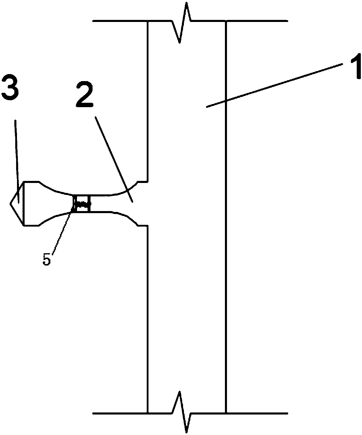
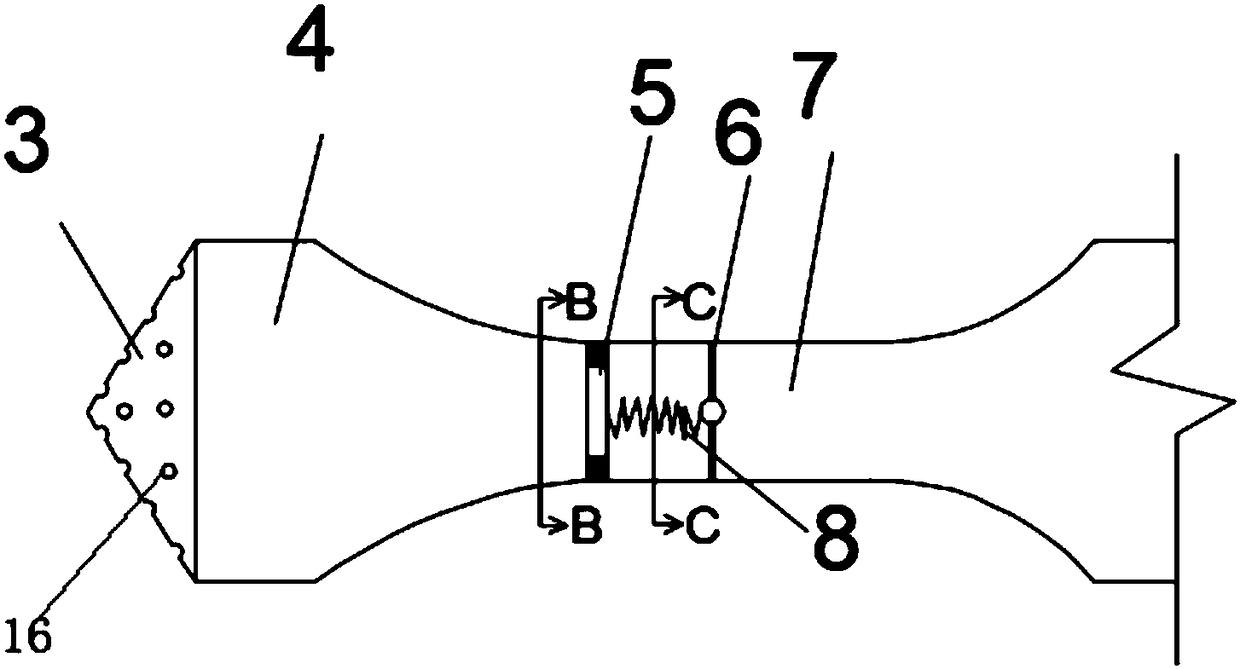
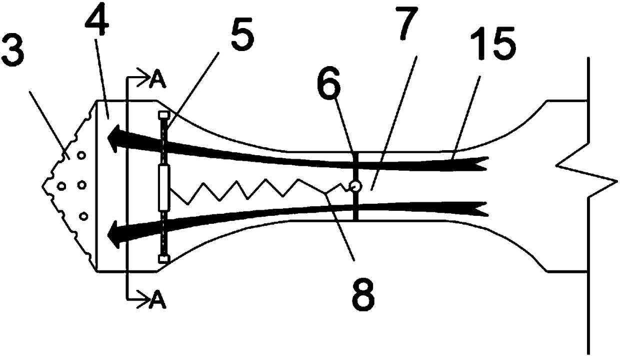
[0045] like figure 1 As shown, a post-grouting device for cast-in-place piles includes a longitudinal grouting main pipe 1, a horizontal grouting branch pipe 2, a grouting head 3 and a one-way check pressure valve 5, and the vertical grouting main pipe 1 The bottom end is closed, and there is an opening on the side of the longitudinal grouting main pipe 1, one end of the horizontal grouting branch pipe 2 is connected to the opening on the longitudinal grouting main pipe 1, and the grouting head 3 is installed on the horizontal grouting branch pipe 2 The other end of the horizontal grouting branch pipe 2 is divided into a middle small section section 7 and a large section section 4 at both ends, and the middle small section section 7 is respectively connected with the large section section 4 at both ends through a smooth necking section, The one-way check pressure valve 5 is installed at the middle small-section section 7 of the horizontal grouting branch pipe 2. When the one-w...


PUM


Abstract

The invention discloses a cast-in-place pile side post-grouting device and method. A high pressure grouting manner is adopted for a pile body through a longitudinal grouting main pipe, a horizontal grouting branch pipe, a taper grouting head and a one-way non-return pressure valve, a pile body mud cake and soil around a pile are strengthened, and the aim of improving the pile foundation bearing force is achieved. The taper grouting head with holes is kept outside the pile body all the time or located on the surface layer of pile body concrete, and reinforcement corrosion hidden dangers causedby excessive damage of the pile body concrete in the grouting process can be avoided; variable cross-section design is adopted for the horizontal grouting branch pipe; the one-way non-return pressurevalve can be controlled to be opened or closed according to the grouting pressure, and silt regurgitation is prevented; and the cast-in-place pile side post-grouting device and the implementation method are suitable for cast-in-place piles with various soil layers, different pile diameters and different pile lengths, the construction technology is simple, the construction method and materials usedby construction are flexible and varied, and popularization and spreading are facilitated.

Description

technical field [0001] The invention relates to the technical field of pile foundation engineering and pile foundation reinforcement, in particular to a post-grouting device and method for pile sides of cast-in-situ piles. Background technique [0002] In modern pile foundation engineering, cast-in-situ piles are very common, especially in some coastal areas, where the depth of underground rock formations is large, and end-bearing piles cannot be used as the main foundation form in the construction of high-rise buildings. Friction piles are used as the main foundation form under such conditions. base form. Most of the friction piles are cast-in-situ piles, so the side friction of the pile foundation determines the bearing capacity of the pile foundation. In order to enhance the pile side friction, the pile side post-grouting device and technology can be used to reinforce the pile side mud skin and A certain range of soil around the pile body can enhance the side resistance ...

Claims


Application Information

Patent Timeline
Patent Type & Authority Applications(China)
IPC IPC(8): E02D5/34
CPCE02D5/34Y02E10/50
Inventor 陈家骐胡明明华建兵段园煜司大雄孙爱琴
Owner HEFEI UNIV
Why Eureka
Try Eureka