Reinforced Concrete Continuous Rigid Frame Bridge Compositely Reinforced by Tension Surface and Its Construction Method

A reinforced concrete, layer composite technology, applied in bridges, bridge parts, bridge construction and other directions, can solve problems such as accidental deformation of bridges, hidden dangers of bridge durability problems, differences in stress distribution, etc., to increase load capacity and ductility. Improve safety and durability, improve the effect of cracking bending moment

Active Publication Date: 2017-01-11
西藏自治区交通勘察设计研究院 +1
View PDF9 Cites 0 Cited by
  • Summary
  • Abstract
  • Description
  • Claims
  • Application Information

AI Technical Summary

Problems solved by technology

[0002] For curved, sloped and oblique continuous rigid frame bridges with large longitudinal slopes and small radius flat curves in some areas with medium and small spans, in order to avoid corrosion of steel bars caused by tensile cracking of concrete structures, prestressing is usually used in conventional designs. To counteract the tensile stress of the bridge under load, due to the complex spatial mechanical behavior of curved, slope, and oblique continuous rigid-frame bridges with medium and small spans, it is necessary to use flat, vertical, and horizontal three-dimensional curved spatial prestressed beams or long and short prestressed beams. In the complex prestressed beam distribution system combined with stress beams, especially in mountainous areas with weak construction technology, there are often obvious differences between the stress distribution of the bridge obtained in actual construction and the designed ideal structure, resulting in unexpected deformation and cracking of the bridge
Especially the existence of cracks on the top surface of the bridge slab in the negative bending moment section of the main girder. The main reinforcement of the bending moment plays a direct corrosion role, and the sensitivity of the prestressed steel wire to crack corrosion will make the bridge have a hidden danger of durability
It is difficult for the construction team to build this kind of non-major bridge in the mountainous area where the bridge construction conditions and technical strength are very limited to meet such high construction technical requirements, and it is easy to cause obvious differences between the actual bridge and the designed ideal bridge, which will lead to hidden dangers of bridge diseases in the later stage

Method used


Image

  • Reinforced Concrete Continuous Rigid Frame Bridge Compositely Reinforced by Tension Surface and Its Construction Method
  • Reinforced Concrete Continuous Rigid Frame Bridge Compositely Reinforced by Tension Surface and Its Construction Method
  • Reinforced Concrete Continuous Rigid Frame Bridge Compositely Reinforced by Tension Surface and Its Construction Method

Examples


Embodiment 1

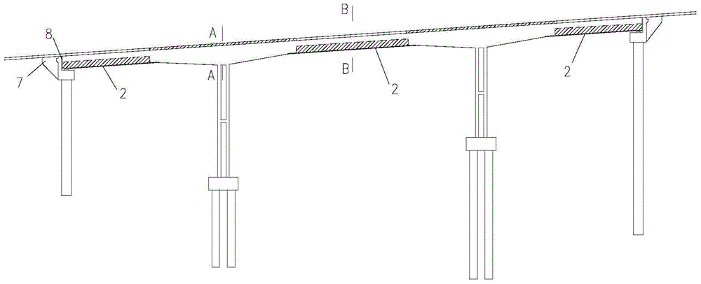
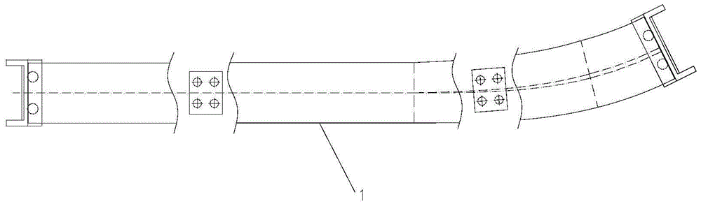
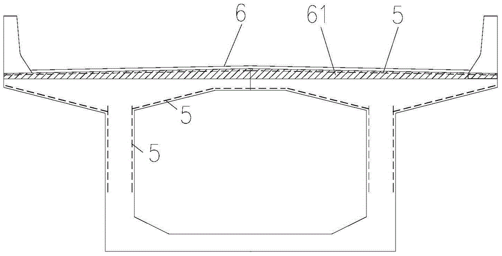
[0030] As shown in the figure: the reinforced concrete continuous rigid frame bridge reinforced by the tension surface layer of the present embodiment includes pier, abutment 7, reinforced concrete girder 1 and bridge deck 6, and the pier top of the main girder 1 is negatively bent The moment section is a box-shaped beam structure, the positive moment section of the main beam 1 is a Π-shaped section beam structure, and the bottom surface of the beam rib of the positive moment section is provided with a steel plate reinforcement layer 2 fixedly connected to the stirrup 11 and the main girder 1 is poured from composite concrete evenly mixed with flexible fibers; the steel plate reinforcement layer 2 is connected to the bottom edge of each stirrup 11 by welding; the steel plate reinforcement layer 2 may include a steel plate body and a longitudinally fixed On the rib plate on the steel plate body, the rib plate is provided with connecting holes for the hoops 11 to pass through. Af...

Embodiment 2

[0043] The difference between this embodiment and Embodiment 1 is only the composition of the filler material for the expansion joint 8. In this embodiment, the filler material in the expansion joint 8 includes 22 parts by weight of red mud, 8 parts of neoprene, 15 parts Polymethyl methacrylate, 5 parts sodium lauryl sulfate, 6 parts hydroxypropyl methylcellulose, 4 parts FERRO fiber, 7 parts steel fiber, 6 parts n-butanol, 5 parts monoalkoxy pyrophosphate ester, 3 parts of methyl tributyl ketoxime silane, 3 parts of trimethylolpropane and 1.5 parts of diisooctyl phthalate; after testing, the 28d compressive strength of the filler material of this composition is 86MPa, and the 28d flexural strength The strength is 8MPa, meeting the requirements of C55 / 65.

Embodiment 3

[0045] The difference between this embodiment and Embodiments 1 and 2 is only the composition of the filler material for the expansion joint 8. In this embodiment, the filler material in the expansion joint 8 includes 25 parts by weight of red mud, 10 parts of neoprene, 20 parts of polymethyl methacrylate, 8 parts of sodium lauryl sulfate, 8 parts of hydroxypropyl methylcellulose, 6 parts of FERRO fiber, 10 parts of steel fiber, 9 parts of n-butanol, 7 parts of monoalkoxy Pyrophosphate, 4 parts of methyl tributylketoxime silane, 4 parts of trimethylolpropane and 3 parts of diisooctyl phthalate; after testing, the compressive strength of the filler material of this composition is 82MPa at 28d, and the compressive strength at 28d The flexural strength is 7MPa, meeting the requirements of C55 / 65.


PUM


Abstract

The invention discloses a tension face layer compound-reinforced reinforced concrete continuous rigid frame bridge and a construction method thereof. The continuous rigid frame bridge comprises a bridge pier, an abutment, a reinforced concrete girder and a bridge floor. The pier top hogging moment section of the girder is of a box-shaped section beam structure, a sagging moment section of the girder is of an n-shaped section beam structure, the bottom surface of a sagging moment section beam rib is provided with a steel plate reinforcement layer fixedly connected to a stirrup, and the girder is formed by pouring composite concrete evenly doped with a flexible material. The tension face layer compound-reinforced reinforced concrete continuous rigid frame bridge is simple to construct and clear in stress, can meet the requirements of crack resistance and crack stopping needed for durability of the concrete bridge, and is suitable for being applied to bent, sloping and inclined concrete continuous rigid frame bridges of medium and small spans where concrete tension and cracking cannot be overcome by pre-stressed strand arrangement easily.

Description

technical field [0001] The invention relates to a bridge and a construction method thereof, in particular to a reinforced concrete continuous rigid frame bridge with composite reinforced tension surface layers and a construction method thereof. Background technique [0002] For curved, sloped and oblique continuous rigid frame bridges with large longitudinal slopes and small radius flat curves in some areas with medium and small spans, in order to avoid corrosion of steel bars caused by tensile cracking of concrete structures, prestressing is usually used in conventional designs. To counteract the tensile stress of the bridge under load, due to the complex spatial mechanical behavior of curved, slope, and oblique continuous rigid-frame bridges with medium and small spans, it is necessary to use flat, vertical, and horizontal three-dimensional curved spatial prestressed beams or long and short prestressed beams. In the complex prestressed beam distribution system combined wit...

Claims


Application Information

Patent Timeline
Patent Type & Authority Patents(China)
IPC IPC(8): E01D2/04E01D19/12E01D19/08E01D19/06E01D21/00
Inventor 周志祥次仁拉姆杨小波王晓东穷达落桑慈成罗东李成君郑佳艳黄雅意曾兴祁
Owner 西藏自治区交通勘察设计研究院
Why Eureka
Try Eureka