Battery set core voltage sampling circuit

A technology of voltage sampling and battery packs, applied in the direction of measuring electricity, measuring electrical variables, measuring devices, etc., can solve the problems of expensive chips, poor scalability, and high cost, and achieve enhanced anti-interference and safety, low cost, Effect of Preventing Leakage Current Problems

Pending Publication Date: 2018-08-28
骆驼集团武汉光谷研发中心有限公司
View PDF0 Cites 3 Cited by
  • Summary
  • Abstract
  • Description
  • Claims
  • Application Information

AI Technical Summary

Problems solved by technology

However, these chips only support 12 strings of battery voltage acquisition at most, and more than 12 strings need to be real

Method used


Image

  • Battery set core voltage sampling circuit
  • Battery set core voltage sampling circuit
  • Battery set core voltage sampling circuit

Examples


Embodiment 1

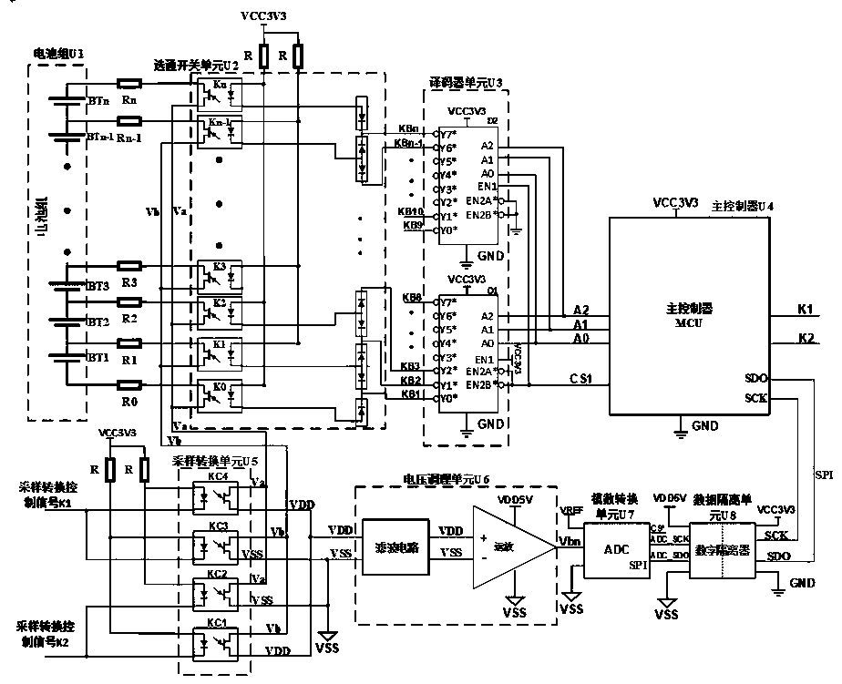
[0022] Example 1 as figure 2 shown. The battery pack U1 is composed of n single cells connected in series, including but not limited to lithium iron phosphate battery packs and ternary (NCM, NCA) lithium battery packs. The positive pole and negative pole of each battery cell in the battery pack U1 are connected to the collector (c pole) of the output terminal of the strobe switch through a series sampling resistor, and the positive and negative poles of n cells in the battery pack U1 are connected to the gate switch The n+1 isolation switches in unit U2 correspond to each other.

[0023] The gating switch unit U2 is composed of an isolating switch array of K0~Kn and a common anode diode array. The isolating switch includes but is not limited to optocoupler and optocoupler relay. The output collectors (c poles) of the isolation switch array K0~Kn are connected to the positive and negative poles of the cells in the battery pack U1 in one-to-one correspondence, and the output ...

Embodiment 2

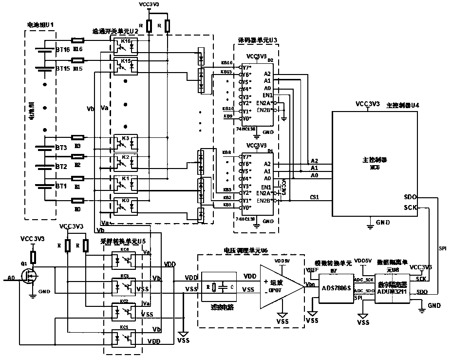
[0050] Example 2 as image 3 shown. According to the basic design idea of ​​embodiment 1, the circuit can be changed into embodiment 2 with a little change.

[0051] The circuit formed by replacing the sampling conversion control signal K1K2 of the MCU with the gating control signal A0 in Embodiment 2 can also realize the gating control of the sampling conversion unit U5. The corresponding changes in the working principle of Embodiment 2 are: when A=0 (sampling of odd-numbered cells), MOS transistor Q1 is turned off, KC1 and KC2 in the sampling conversion unit U5 are turned on, KC3 and KC4 are turned off, and K1K2=10 is realized The effect is the same; when A=1 (even cell sampling), MOS transistor Q1 is turned on, KC1 and KC2 in the sampling conversion unit U5 are turned off, KC3 and KC4 are turned on, and the effect is the same as K1K2=01. The working principle of other parts of Embodiment 2 is the same as that of Embodiment 1, and will not be repeated here.


PUM


Abstract

The name of the invention is a battery set core voltage sampling circuit, belongs to the technical field of a battery management system and mainly aims to solve problems of poor anti-interference property, poor stability and bad influence on consistency and the service life caused by the continuous leakage current of batteries because of having no isolation between a core voltage sampling circuitin the prior art and a voltage dividing sampling resistor. The battery set core voltage sampling circuit is mainly characterized by comprising a battery set, a gate switch unit, a decoder unit, a maincontroller, a sampling conversion unit, a voltage conditioning unit, an analog to digital conversion unit and a data isolation unit, wherein the gate switch unit and the sampling conversion unit areconnected through buses Va and Vb, the voltage conditioning unit is composed of a filter circuit and a negative feedback amplifying circuit, the negative feedback amplifying circuit is supplied with power through an isolation power source, and the power source ground is connected with a signal of the sampling conversion unit with a low sampling output voltage. The battery set core voltage samplingcircuit is advantaged in that good anti-interference property, good safety, strong scalability and relatively low cost are realized, and the battery set core voltage sampling circuit is mainly used for sampling and detecting multiple single cores of the battery set.

Description

technical field [0001] The invention belongs to the technical field of battery management systems. In particular, it relates to a lithium-ion battery cell voltage sampling circuit. Background technique [0002] Lithium-ion battery packs are composed of multiple single cells connected in series and parallel. Due to the short circuit, overcharge, overdischarge, and poor voltage consistency of the single cells, the performance of the battery will decline and the life will attenuate, and even the It will cause serious safety hazards such as smoke, fire and explosion. Therefore, the lithium-ion battery pack must detect the voltage of each single cell in real time during use, so as to accurately control and protect the charging and discharging process of the battery pack. [0003] At present, there are two commonly used battery cell voltage sampling methods in the market. The first method uses the common mode voltage division method to sample the cell voltage of the battery pack...

Claims


Application Information

Patent Timeline
IPC IPC(8): G01R31/36
CPCG01R31/3835
Inventor 姜欢刘金松刘道坦吴志威夏诗忠刘长来
Owner 骆驼集团武汉光谷研发中心有限公司
Why Eureka
Try Eureka