
A single-stage single-phase boost inverter with an inverter bridge magnetically coupled energy storage inductor

A technology of energy storage inductance and magnetic coupling, applied in electrical components, output power conversion devices, AC power input conversion to DC power output, etc., can solve the problem of increasing circuit complexity, loss and cost, increasing volume, weight and cost , system utilization rate decline and other issues, to achieve the effect of low cost, solve the problem of loss, and high reliability

Inactive Publication Date: 2020-05-08
FUZHOU UNIV
View PDF2 Cites 0 Cited by
  • Summary
  • Abstract
  • Description
  • Claims
  • Application Information

AI Technical Summary

Problems solved by technology

When this type of inverter works normally, the voltage on the DC side must be greater than the peak value of the phase voltage on the AC side, so there is an obvious defect: when the voltage on the DC side (such as the output capacity of photovoltaic cells) decreases, such as in rainy days or at night, the entire power generation The system will stop functioning and the utilization of the system will drop
In this regard, the following two methods are often used to solve this problem: (1) adding a Boost DC converter in the front stage to form a two-stage power conversion circuit structure, which increases the complexity, loss and cost of the circuit; (2) ) output plus a single-phase power frequency transformer, thus greatly increasing the volume, weight and cost of the system, especially difficult to adapt to today's sharp rise in the price of copper and iron raw materials

Method used


Image

  • A single-stage single-phase boost inverter with an inverter bridge magnetically coupled energy storage inductor
  • A single-stage single-phase boost inverter with an inverter bridge magnetically coupled energy storage inductor
  • A single-stage single-phase boost inverter with an inverter bridge magnetically coupled energy storage inductor

Examples


Embodiment Construction

[0031] The present invention will be further described below in conjunction with the accompanying drawings and embodiments.

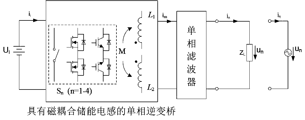
[0032] Such as figure 1 As shown, this embodiment provides a single-stage single-phase boost inverter with a magnetically coupled energy storage inductor of an inverter bridge, including a single-phase inverter bridge with a magnetically coupled energy storage inductor cascaded in sequence and Single-phase filter; the single-phase inverter bridge with magnetically coupled energy storage inductors includes two fully magnetically coupled energy storage inductors with the same parameters, and four four-quadrant power switches capable of withstanding bidirectional voltage stress and bidirectional current stress .

[0033] Wherein, the bridge arm of the single-phase inverter bridge with magnetically coupled energy storage inductance adopts a four-quadrant power switch capable of withstanding bidirectional voltage stress and bidirectional current stress; the...


PUM


Abstract

The invention relates to a monopole and single-phase boost inverter having a magnetic coupling energy storage inductor of an inversion bridge. The monopole and single-phase boost inverter comprises asingle-phase inversion bridge and a single-phase filter which are sequentially cascaded, wherein the single-phase inversion bridge is provided with the magnetic coupling energy storage inductor, the single-phase inversion bridge with the magnetic coupling energy storage inductor comprises two energy storage inductors and four four-quadrant power switches, the energy storage inductors are completely and magnetically coupled and are same in parameter, and the four-quadrant power switches can bear bidirectional voltage stress and bidirectional current stress. The monopole and single-phase boost inverter has the advantages of monopole boost power conversion, high power density, high conversion efficiency, bidirectional power flow, low output waveform distortion degree, high reliability duringoverload and short circuit, low cost and the like, is suitable for boost and medium- and small-capacity single-phase passive and grid-connected inversion occasions, and the unique advantage is more shown with a new device such as a bidirectional IGBT which can be blocked.

Description

technical field [0001] The invention belongs to the power electronic technology, in particular to a single-stage single-phase boost inverter with an inverter bridge magnetic coupling energy storage inductance. Background technique [0002] The inverter is a static conversion device that uses power semiconductor devices to convert direct current into alternating current, which is used for AC loads or connected to the public grid for power generation. [0003] Due to the increasing shortage of fossil energy (non-renewable energy) such as oil, coal and natural gas, serious environmental pollution, global warming, nuclear waste and environmental pollution caused by nuclear energy production, energy and the environment have become major issues facing mankind in the 21st century. . Renewable energy (green energy) such as solar energy, wind energy, tidal energy and geothermal energy has the advantages of being clean, pollution-free, cheap, reliable, and abundant. People are paying...

Claims


Application Information

Patent Timeline
Patent Type & Authority Patents(China)
IPC IPC(8): H02M7/797
CPCH02M7/797
Inventor 陈亦文庄学添
Owner FUZHOU UNIV
Learn More