Laser cutting system and cutting method
A technology of laser cutting and cutting method, applied in laser welding equipment, metal processing equipment, welding equipment and other directions, can solve the problem of offset of cutting line, and achieve the effect of improving quality, improving cutting quality and saving cutting time
- Summary
- Abstract
- Description
- Claims
- Application Information
AI Technical Summary
Problems solved by technology
Method used
Image

Examples
Embodiment Construction
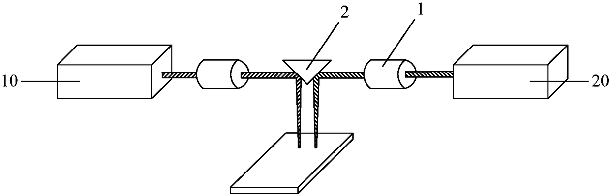
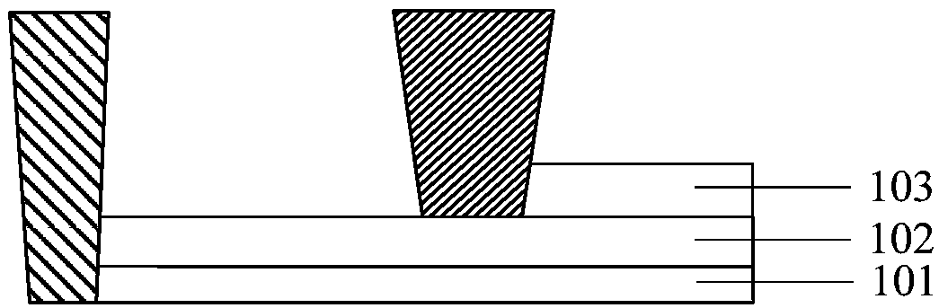
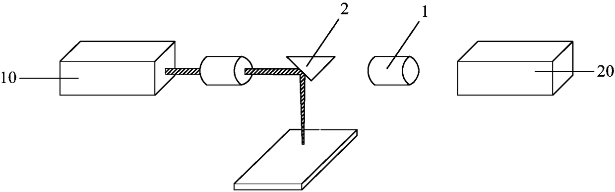
[0030] In the prior art, different laser sources are required to cut different layer structures in the cutting of display screens, and different laser sources are aligned to the same cutting line through different driving mechanisms for cutting, resulting in alignment offsets of different laser sources, which affect the cutting quality .
[0031] In order to solve the above technical problems, the present invention provides a laser cutting system, which can be used but not limited to cutting display screens. The laser cutting system includes at least two laser sources, the at least two laser sources are used to cut different layer structures of the substrate to be cut, and the lasers emitted by the at least two laser sources cut the to-be-cut substrate along the first cutting line. substrate. Wherein, the positions of the at least two laser sources are relatively fixed, and the laser light emitted by the at least two laser sources is projected onto the substrate to be cut, an...
PUM
 Abstract
Description
Claims
Application Information
 - Generate Ideas
- Intellectual Property
- Life Sciences
- Materials
- Tech Scout
- Unparalleled Data Quality
- Higher Quality Content
- 60% Fewer Hallucinations
Browse by: Latest US Patents, China's latest patents, Technical Efficacy Thesaurus, Application Domain, Technology Topic, Popular Technical Reports.
© 2025 PatSnap. All rights reserved.Legal|Privacy policy|Modern Slavery Act Transparency Statement|Sitemap|About US| Contact US: help@patsnap.com