High-water-head and high-flow energy dissipation and pressure reduction drainage system of long water diversion power station

A technology for drainage systems and hydropower stations, applied in hydropower stations, hydropower generation, water conservancy projects, etc., can solve problems such as high operator requirements, damage to turbine overcurrent components, and large investment, achieving good flow regulation characteristics and decompression effects. Good, large drainage effect

Active Publication Date: 2018-08-31
CHANGJIANG SURVEY PLANNING DESIGN & RES
View PDF4 Cites 0 Cited by
  • Summary
  • Abstract
  • Description
  • Claims
  • Application Information

AI Technical Summary

Problems solved by technology

The construction of special maintenance and drainage tunnels is limited by factors such as terrain and geological conditions, and there are adverse effects such as difficult construction, large investment, and large areas affected by the drainage period.
If the way of discharge through the machine is adopted, the power station of the long water diversion system needs the hydro-generator set to keep idling for a long time. Manufacturers of turbine generator sets generally do not allow the operating unit to operate in this way on the grounds of the safe and stable operation of the unit
In addition, after the first water filling test, there may be more sediment and stones in the diversion tunnel, and the direct discharge through the unit will cause damage to the flow parts of the turbine

Method used


Image

  • High-water-head and high-flow energy dissipation and pressure reduction drainage system of long water diversion power station
  • High-water-head and high-flow energy dissipation and pressure reduction drainage system of long water diversion power station
  • High-water-head and high-flow energy dissipation and pressure reduction drainage system of long water diversion power station

Examples


Embodiment Construction

[0017] The implementation of the present invention will be described in detail below in conjunction with the accompanying drawings, but they do not constitute a limitation to the present invention, they are only examples, and at the same time, the advantages of the present invention will become clearer and easier to understand.

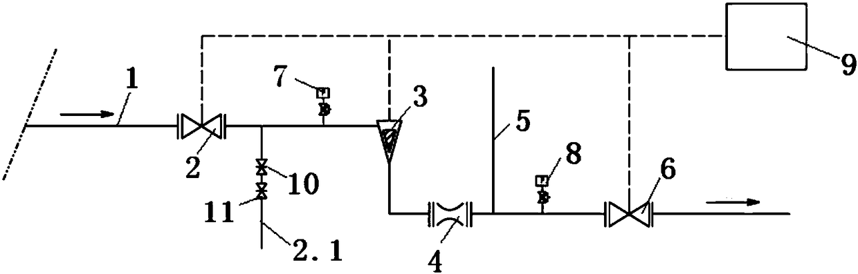
[0018] refer to figure 1 Shown: a long diversion hydropower station with high head and large flow energy dissipation and decompression drainage system, which includes a drainage pipe 1 arranged along the end of the diversion tunnel to the downstream tailrace tunnel, and the drainage pipe 1 is sequentially equipped with hydraulic control ball valves 2, The hydraulic control needle valve 3, the eccentric swirl device 4, the air supply pipe 5 and the hydraulic control knife valve 6; the first pressure transmitter 7 is installed between the hydraulic control ball valve 2 and the hydraulic control needle valve 3, and the A second pressure transmitter 8 is ...


PUM


Abstract

The invention discloses a high-water-head and high-flow energy dissipation and pressure reduction drainage system of a long water diversion power station. The high-water-head and high-flow energy dissipation and pressure reduction drainage system of the long water diversion power station comprises a drainage pipeline (1), wherein the drainage pipeline (1) is arranged to a downstream tailwater tunnel along the tail end of a water diversion tunnel. A hydraulic control ball valve (2), a hydraulic control needle valve (3), an eccentric rotational flow device (4), a gas supplementing pipe (5) and ahydraulic control cutter valve (6) are installed on the drainage pipeline (1) in sequence. A first pressure transmitter (7) is installed between the hydraulic control ball valve (2) and the hydrauliccontrol needle valve (3), and a second pressure transmitter (8) is installed between the gas supplementing pipe (5) and the hydraulic control cutter valve (6). The high-water-head and high-flow energy dissipation and pressure reduction drainage system of the long water diversion power station overcomes the defect that in the prior art, lots of silt and stones possibly exist in the water diversiontunnel after a water filling test is accomplished for the first time, and can cause damage to flow passing parts of a water turbine when the water containing silt and the stones is directly discharged through a unit. The high-water-head and high-flow energy dissipation and pressure reduction drainage system of the long water diversion power station has the advantages that due to the fact that thebefore-and-after pressure difference of a core pressure reduction part is monitored, the valve opening of the hydraulic control needle valve is adjusted in real time, and automatic adjustment and control of the flow and the pressure are achieved.

Description

technical field [0001] The invention relates to the field of electromechanical technology of water conservancy and hydropower engineering, and more specifically relates to a long-diversion hydropower station high-head and large-flow energy-dissipating and pressure-reducing drainage system. Background technique [0002] For a hydropower station with a long water diversion system, when the diversion tunnel needs to be inspected after the first water filling test of the power station or after many years of operation, it is necessary to drain the accumulated water in the diversion system so that the staff can enter the flow channel for inspection and maintenance. The water diversion system of a power station with long water diversion and high water head has a large displacement and high drainage pressure. It is urgent to develop a drainage system that is safe, fast, and effective in dissipating energy without causing impact on downstream facilities. [0003] Conventional water d...

Claims


Application Information

Patent Timeline
Patent Type & Authority Applications(China)
IPC IPC(8): E02B9/06
CPCE02B9/06Y02E10/20
Inventor 何志锋刘景旺陈冬波郑涛平胡定辉田子勤易先举段威金德山代开锋柳飞何昌炎
Owner CHANGJIANG SURVEY PLANNING DESIGN & RES
Why Eureka
Try Eureka