Circulating working medium heat exchanger with oil separation function and application thereof

A circulating working fluid and oil separation technology, which is applied in the direction of machines/engines, steam turbines, mechanical equipment, etc., can solve problems such as the inability to monitor the concentration and temperature of lubricating oil, the low lubricating effect, and the large space occupied by equipment. , to achieve the effect of lowering the temperature, compact structure and saving energy

Inactive Publication Date: 2018-08-31
SOUTHEAST UNIV
View PDF0 Cites 3 Cited by
  • Summary
  • Abstract
  • Description
  • Claims
  • Application Information

AI Technical Summary

Problems solved by technology

[0005] In the traditional organic Rankine cycle system with oil separator and regenerator, the oil separator and regenerator are two separate devices, the system is relatively complicated, and the heat recovered by the regenerator starts after the oil separator , the heat recovery efficiency is low, and the equipment occupies a large space
[0006] The structure of the traditional oil separator is relatively simple, and the function is relatively single. In the case of continuous operation of the expander, the temperature of the lubricating oil is very high, so that the viscosity reduction performance is reduced; To achieve a good lubricating effect, the traditional oil separator cannot monitor the concentration and temperature of the lubricating oil, and it can heat and cool the lubricating oil in time

Method used


Image

  • Circulating working medium heat exchanger with oil separation function and application thereof
  • Circulating working medium heat exchanger with oil separation function and application thereof

Examples


Embodiment Construction

[0034] The present invention will be further described below in conjunction with the accompanying drawings and embodiments.

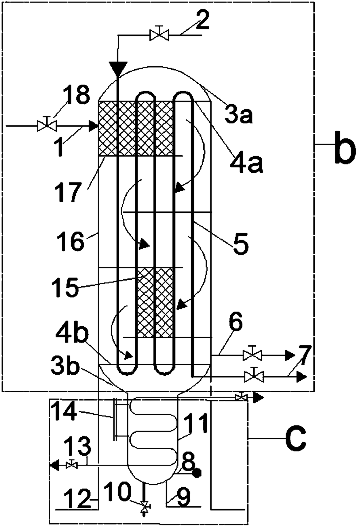
[0035] A circulating working medium heat exchanger with oil separation function includes an oil separation heat exchange device b and a heat exchange oil storage device c, the oil separation heat exchange device b is placed above the heat exchange oil storage device c and the two In the same way, the oil separation and heat exchange device b uses the liquid-phase working fluid to recover waste heat from the gas-phase working fluid and at the same time separates the lubricating oil mixed in the gas-phase working fluid, and the heat exchange and oil storage device c stores the separated lubricating oil and has the function of exchanging The heat exchange tube 13 of the thermal oil storage device has the effect of heating and cooling the lubricating oil;

[0036] The oil separation heat exchange device b includes a shell 16, and an upper tube plate 4a and ...


PUM


Abstract

The invention discloses a circulating working medium heat exchanger with an oil separation function and application thereof. The circulating working medium heat exchanger with the oil separation function comprises an oil separation heat exchange device (b) and a heat exchange oil storage device (c) placed below the oil separation heat exchange device (b), and the oil separation heat exchange device and the heat exchange oil storage device communicate with each other; a screen filter element assembly (15) is arranged inside the oil separation heat exchange device (b) to integrate the oil separation and the heat exchanger functions together, and materials of equipment and the occupied space are saved; and liquid phase working medium is used for recycling waste heat from gas phase working medium, lubricating oil is separated from the gas phase working medium at the same time, the separated lubricating oil is stored in a cylinder body of the heat exchange oil storage device, and a heat exchange tube in the cylinder body is used for heating and cooling the lubricating oil. The heat exchanger is applied to an organic Rankine circulatory system (d) to reduce the temperature of the gas phase working medium at an outlet of a volumetric-type expansion machine (19), and the oil separation effect is improved while the thermal efficiency of the system is improved.

Description

technical field [0001] The invention relates to a circulating working fluid heat exchanger with oil separation function and its application, belonging to the technical field of energy. Background technique [0002] One of the ways to solve the problem of energy shortage in today's society is to make full use of various waste heat resources and develop and utilize renewable energy such as geothermal energy and solar energy. The organic Rankine cycle system is simple, and has a high recycling rate for heat sources such as geothermal heat, solar energy, factory waste heat, and generator waste heat. A general organic Rankine cycle expander system (ORC) is composed of important equipment such as expander, oil separator, condenser, liquid receiver, working fluid pump, regenerator and evaporator. [0003] In the organic Rankine cycle system, the exhaust gas regenerator extracts the working medium in the expander to heat the condensed working medium, and increases the temperature o...

Claims


Application Information

Patent Timeline
Patent Type & Authority Applications(China)
IPC IPC(8): F01K25/08F01K21/00
CPCF01K25/08F01K21/00
Inventor 陈九法王楠麻建超庄昆明王晓奇
Owner SOUTHEAST UNIV
Why Eureka
Try Eureka