Non-aqueous lithium storage element

A technology for electric storage components and non-aqueous electrolytes, which is applied to lithium batteries, electrical components, non-aqueous electrolyte batteries, etc., and can solve problems such as the suppression of internal short-circuit thermal runaway without consideration

Active Publication Date: 2019-08-02
ASAHI KASEI KK
View PDF16 Cites 0 Cited by
  • Summary
  • Abstract
  • Description
  • Claims
  • Application Information

AI Technical Summary

Problems solved by technology

However, in the electrode described in Patent Document 4, the suppression of thermal runaway during internal short circuit is not considered at all.

Method used


Image

  • Non-aqueous lithium storage element
  • Non-aqueous lithium storage element
  • Non-aqueous lithium storage element

Examples


preparation example Construction

[0303] Regarding the preparation of the coating liquid, a part or all of various material powders containing the negative electrode active material may be dry-blended, followed by adding water or an organic solvent, and / or dissolving or dispersing a binder or a dispersion stabilizer in them. A liquid or slurry-like substance is used to prepare a coating solution. Alternatively, a binder or a dispersion stabilizer may be dissolved or dispersed in water or an organic solvent, and various material powders including a negative electrode active material may be added to the obtained liquid or slurry to prepare a coating liquid.

[0304] The method of dissolution or dispersion is not particularly limited, and dispersing machines such as a homodisperser, a multi-shaft disperser, a planetary mixer, and a thin-film rotary high-speed mixer, etc., can be suitably used. In order to obtain a coating liquid in a good dispersion state, it is preferable to disperse at a peripheral speed of 1 m...

Embodiment 1

[0559]

preparation example 1a

[0561] Put the crushed coconut shell carbides into a small carbonization furnace, and carry out carbonization treatment at 500°C for 3 hours under nitrogen atmosphere to obtain carbides. Put the obtained carbide into the activation furnace, introduce the water vapor obtained by heating with the preheating furnace into the activation furnace at 1 kg / h, and raise the temperature to 900°C for 8 hours for activation. The activated carbide was taken out and cooled under a nitrogen atmosphere to obtain activated activated carbon. The obtained activated carbon was washed with water for 10 hours to remove water, dried in an electric dryer kept at 115° C. for 10 hours, and pulverized with a ball mill for 1 hour to obtain activated carbon 1 .

[0562] The average particle diameter of the activated carbon 1 was measured using a laser diffraction particle size distribution analyzer (SALD-2000J) manufactured by Shimadzu Corporation, and it was 4.2 μm. Moreover, the pore distribution of th...


PUM

PropertyMeasurementUnit
specific surface areaaaaaaaaaaa
particle sizeaaaaaaaaaa
thicknessaaaaaaaaaa

Abstract

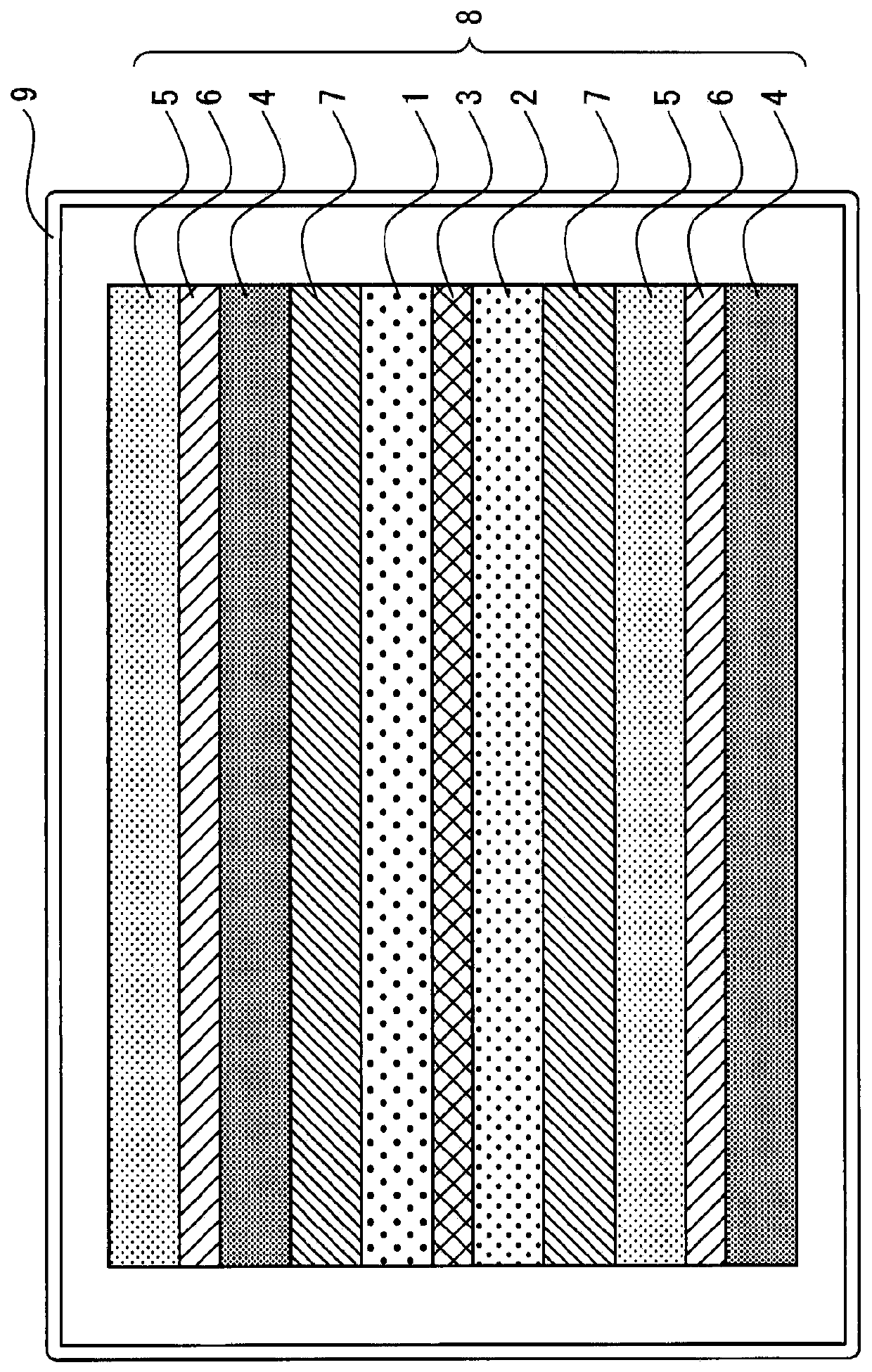
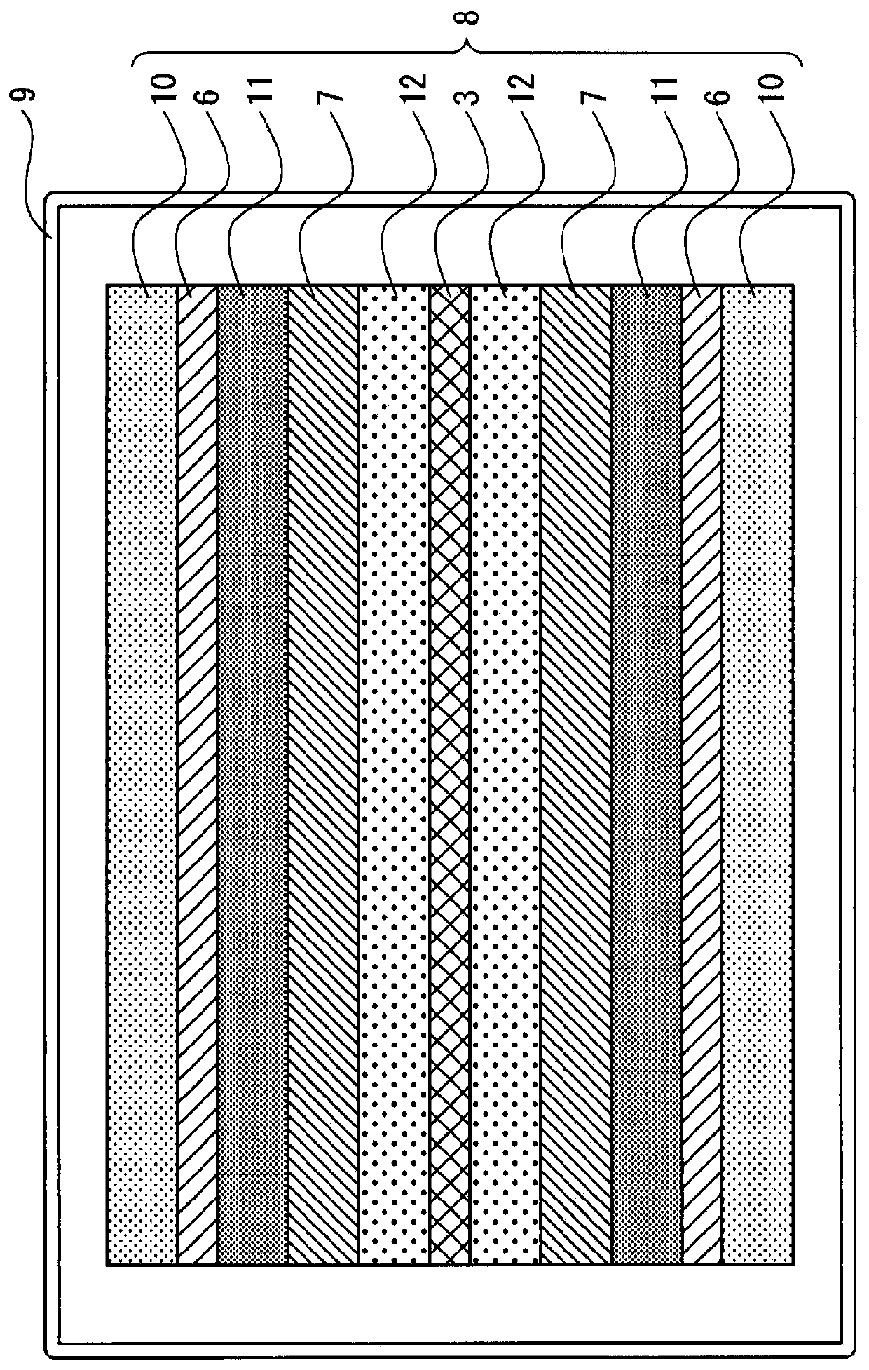
The lithium storage device of the present invention includes a positive electrode, a negative electrode, a separator, and a non-aqueous electrolytic solution, the positive electrode contains a lithium compound other than an active material, the non-aqueous electrolytic solution contains lithium ions, and the non-porous positive electrode collects electricity Active material is coated on both sides of the body, and a negative active material capable of absorbing and releasing lithium ions is coated on both sides of the non-porous negative electrode current collector; the positive active material layer C x The base weight of the face is C x1 , the positive electrode active material layer C on the other side y The base weight of the face is C y1 , will be compared with C y Facing negative electrode active material layer A y The base weight of the face is A y1 , the other side is the negative electrode active material layer A x The base weight of the face is A x1 , the C x The amount of lithium compound per unit area of ​​the surface is set to C x2 , the C y The amount of lithium compound per unit area of ​​the surface is set to C y2 , satisfy the following formula. 0.85≤C x1 / C y1 ≤1.15, 0.85≤A x1 / A y1 ≤1.15, 0.80≤(A x1 +C x1 ) / (A y1 +C y1 )≤1.20, 0.1≤C x2 (g / m 2 )≤18, 0.1≤C y2 (g / m 2 )≤18, 0.60≤C y2 / C x2 ≤1.70, 0.60≤C x2 / C y2 ≤1.70.

Description

[0001] 【Technical field】 [0002] The invention relates to a non-aqueous lithium storage element. [0003] 【Background technique】 [0004] In recent years, from the perspective of protecting the global environment and saving resources and effectively using energy, wind power generation power stabilization systems or late-night power storage systems, household distributed power storage systems based on photovoltaic power generation technology, and electric vehicles Power storage systems and the like are attracting attention. [0005] The first requirement for batteries used in these power storage systems is high energy density. As a powerful supplement to high-energy-density batteries that can meet such demands, development of lithium-ion batteries has been actively promoted. [0006] The second required item is high output characteristics. For example, in a combination of a high-efficiency engine and a power storage system (such as a hybrid electric vehicle), or a combinatio...

Claims


Application Information

Patent Timeline
Patent Type & Authority Patents(China)
IPC IPC(8): H01M4/1393H01M10/052H01M10/0567H01M10/0585
CPCH01G11/06H01G11/24H01G11/26H01G11/28H01G11/50H01M4/1393H01M10/052H01M10/0567H01M10/0585Y02E60/10Y02T10/70Y02P70/50H01G11/70H01M4/133H01M4/62H01M10/0525H01M10/0587Y02E60/13
Inventor 梅津和照上城武司平川雄一朗楠坂启太冈田宣宏末富拓
Owner ASAHI KASEI KK
Why Eureka
Try Eureka