Forming method and forming device of a double-layer plate structure

A molding device and molding method technology, applied in the field of parts processing, can solve the problems that the superplastic forming/diffusion bonding process cannot be realized, the temperature difference between superplastic forming and diffusion bonding is large, and the cost is high, so as to achieve shortened processing cycle, low cost, The effect of reducing the cost of production

Active Publication Date: 2020-09-11
CHENGDU AIRCRAFT INDUSTRY GROUP
View PDF5 Cites 0 Cited by
  • Summary
  • Abstract
  • Description
  • Claims
  • Application Information

AI Technical Summary

Problems solved by technology

[0005] The purpose of the present invention is to overcome the above-mentioned problems in the prior art, provide a forming method and forming device for double-layer plate structural parts, solve the problems of high cost and long cycle of the existing forming methods, and can solve the problem of superplastic forming / Manufacture of two-layer plate structural parts of materials with a large temperature difference between superplastic forming and diffusion bonding that cannot be realized by diffusion bonding

Method used


Image

  • Forming method and forming device of a double-layer plate structure
  • Forming method and forming device of a double-layer plate structure

Examples


Embodiment 1

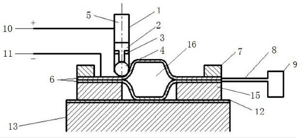
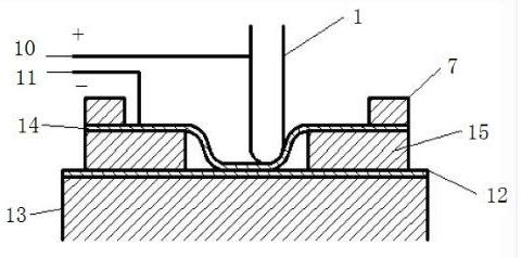
[0037] Such as Figure 1 to 2 As shown, a method for forming a double-layer board structure includes the following steps:

[0038] X1. Cut the material board into multiple pieces by a shearing machine. Place two cushion blocks 15 on the processing platform 13 with a distance between the two cushion blocks 15. Place the cut material board on the cushion block 15 Fix the edge of the material plate on the spacer block 15 by the fixing clamp 7, and the middle part of the material plate covers the space between the two spacer blocks 15;

[0039] X2, the material plate is connected to the negative electrode of the power supply through the negative lead 11, the processing tool head 1 is connected to the positive electrode of the power supply through the positive lead 10, the processing tool head 1 is in contact with the material plate, and the processing tool head 1, the material plate and the power source form a closed loop;

[0040] X3. The current in the loop generates Joule heat on the...

Embodiment 2

[0050] Such as Figure 1 to 2 As shown, a method for forming a double-layer board structure includes the following steps:

[0051] X1. Cut the material board into multiple pieces by a shearing machine. Place two cushion blocks 15 on the processing platform 13 with a distance between the two cushion blocks 15. Place the cut material board on the cushion block 15 Fix the edge of the material plate on the spacer block 15 by the fixing clamp 7, and the middle part of the material plate covers the space between the two spacer blocks 15;

[0052] X2, the material plate is connected to the negative electrode of the power supply through the negative lead 11, the processing tool head 1 is connected to the positive electrode of the power supply through the positive lead 10, the processing tool head 1 is in contact with the material plate, and the processing tool head 1, the material plate and the power source form a closed loop;

[0053] X3. The current in the loop generates Joule heat on the...

Embodiment 3

[0065] Such as Figure 1 to 2 As shown, a method for forming a double-layer board structure includes the following steps:

[0066] X1. Cut the material board into multiple pieces by a shearing machine. Place two cushion blocks 15 on the processing platform 13 with a distance between the two cushion blocks 15. Place the cut material board on the cushion block 15 Fix the edge of the material plate on the spacer block 15 by the fixing clamp 7, and the middle part of the material plate covers the space between the two spacer blocks 15;

[0067] X2, the material plate is connected to the negative electrode of the power supply through the negative lead 11, the processing tool head 1 is connected to the positive electrode of the power supply through the positive lead 10, the processing tool head 1 is in contact with the material plate, and the processing tool head 1, the material plate and the power source form a closed loop;

[0068] X3. The current in the loop generates Joule heat on the...


PUM


Abstract

The invention relates to a forming method and a forming device of doubling plate structural members. The forming device comprises a machining tool head, a machining platform and a plurality of metal plate materials. A fixed clamp and two cushion blocks are installed on the machining platform. Every two corresponding metal plate materials are welded into a workblank piece through argon arc welding.A workblank molding cavity is formed in each workblank piece after welding. Each workblank piece is installed on the corresponding cushion block through the fixed clamp. The machining tool head actson the workblank pieces. The machining tool head is connected with the positive pole of a power source through a positive pole wire. The workblank pieces are connected with the negative pole of the power source through negative pole wires. The workblank piece molding cavities communicate with a vacuum pump through titanium pipes. The workblank pieces are electrified so that heat can be generated,the workblank pieces are heated to the diffusion bonding temperature of the materials through a self-resistance heating mode, the machining tool head moves along a machining track under the control ofNC, no mold is needed in the molding technique of plates, the forming method is low in cost, and the period is shortened.

Description

Technical field [0001] The invention belongs to the technical field of parts processing, and particularly relates to a forming method and a forming device of a double-layer plate structure. Background technique [0002] For two-layer plate structure parts made of superplastic materials such as titanium alloys and aluminum alloys, superplastic forming / diffusion bonding combined processes are often commonly used. The superplastic forming / diffusion bonding combined process only requires one tooling to complete superplastic forming and diffusion bonding. Compared with the traditional forming method, it has certain advantages. However, based on the forming environment of superplastic forming / diffusion bonding process, it has more stringent conditions for the mold, such as good resistance to oxygen scratches and thermal stability of the mold material. Mechanical properties and creep resistance etc. [0003] The patent number is CN201769359U and the filing date is 2010-09-01. It disclose...

Claims


Application Information

Patent Timeline
Patent Type & Authority Patents(China)
IPC IPC(8): B23P15/00B23P23/04
CPCB23P15/00B23P23/04
Inventor 王宇盛姚刚张晶
Owner CHENGDU AIRCRAFT INDUSTRY GROUP
Why Eureka
Try Eureka