
Unmanned aerial vehicle pneumatic catapulting system

An unmanned aerial vehicle and pneumatic technology, which is applied in the direction of launch/drag transmission, can solve the problems of increasing the weight and volume of the launch device, increasing the weight of the launch device, increasing the difficulty of transportation, operation and maintenance, etc., to simplify the difficulty of maintenance and Operation steps, reduction in overall volume and weight, effect of saving volume and weight

Inactive Publication Date: 2018-09-04
YANSHAN UNIV
View PDF8 Cites 5 Cited by
  • Summary
  • Abstract
  • Description
  • Claims
  • Application Information

AI Technical Summary

Problems solved by technology

The deceleration device that exists at present has the rubber band anti-pull type, the pneumatic cylinder is used as the buffer mechanism of the impact buffer, and the mode of using the spring and the buffer block as the buffer mechanism, etc. The patent No. 200610035764. Pull-type deceleration device, this deceleration device is suitable for the deceleration device of the small UAV launching mechanism, the deceleration device of this structure limits the weight of the launching UAV and the speed of the UAV when it takes off; the patent number is 201220258062.9 The launch mechanism of the impact buffer device made of a pneumatic cylinder is used in the device, which increases the weight and volume of the launch device. The device with the patent number 201520134411.X uses a buffer mechanism of a spring and a sliding buffer block. The structure of the mechanism is complex , which also increases the weight of the overall launching device; on the other hand, the return stroke of the pneumatic cylinder basically depends on a separate return mechanism. It will increase the weight of the whole equipment, and the system will become complicated, which will increase the difficulty of transportation, operation and maintenance.

Method used


Image

  • Unmanned aerial vehicle pneumatic catapulting system

Examples


Embodiment Construction

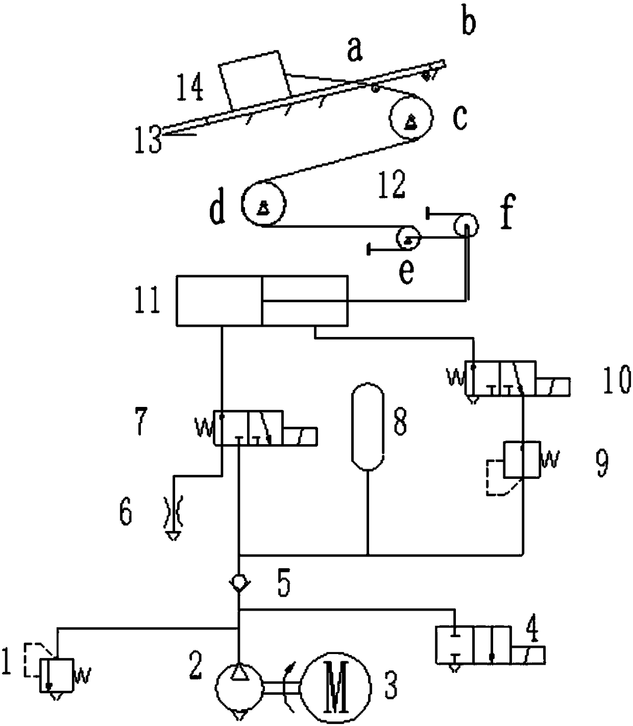
[0012] exist figure 1 In the schematic diagram of the UAV pneumatic ejection system shown in the figure, the launch trolley 14 is placed on the inclined guide rail of the launch frame 13, and the front end of the launch trolley (towards the launch terminal direction) is connected with one end of the main steel wire rope, and the other end of the main steel wire rope passes through The gap between the launching rack guide rails is fixed on the launching rack by bypassing the pulley block 12 that is located at the guide rail below. The pulley assembly includes 5 fixed pulleys and 1 movable pulley, among which the fixed pulleys a and b are set on the guide rail, the fixed pulleys c, d and e are distributed in a "zigzag" shape, and the main steel wire rope is fixed after winding around the last fixed pulley e in some place. One end of the auxiliary steel wire rope is fixed on the axle of the fixed pulley e, and the other end of the auxiliary steel wire rope is fixedly connected o...


PUM


Abstract

The invention provides an unmanned aerial vehicle pneumatic catapulting system. The front end of a launching trolley arranged on launching cradle oblique guide rails is connected with one end of a main steel wire rope. The other end of the main steel wire rope is wound round a pulley component arranged below the guide rails and then fixedly connected to a launching cradle. A rotary shaft of a movable pulley f of the pulley component is connected with a piston rod of an asymmetric pneumatic cylinder of a pneumatic component. A rodless cavity of the asymmetric pneumatic cylinder is connected with a launching stage electromagnetic reversing valve. The electromagnetic reversing valve is further connected with a gas storage bottle and a throttling valve. A rod cavity of the asymmetric pneumaticcylinder is connected with a deceleration and return stroke electromagnetic reversing valve. The deceleration and return stroke electromagnetic reversing valve is further connected with a pressure reducing valve in series. The pressure reducing valve is connected with a gas outlet of the gas storage bottle. The launching stage electromagnetic reversing valve, the pressure reducing valve and the gas storage bottle are all connected with an air compressor and a motor. One pneumatic cylinder is used for achieving launching, decelerating and stroke returning actions, the size and the weight of the whole unmanned aerial vehicle pneumatic catapulting system are greatly reduced, and maintenance is simplified.

Description

technical field [0001] The invention relates to a pneumatic ejection system of an unmanned aerial vehicle. Background technique [0002] A drone is an unmanned aerial vehicle controlled by radar or an onboard program. At present, it is mainly used for intelligence collection, surveillance, as a target drone, signal relay, and attacking targets. UAVs are gradually used in civilian and military fields due to their advantages of simple manufacture, low cost, no fear of sacrifice, and simple take-off and landing. The role is becoming more and more important, and more than 30 countries including the United States have carried out in-depth research on the field of drones. [0003] The take-off methods of UAVs can be divided into spiral-wing take-off, run-to-roll, catapult, rocket-launch, hand throw, vehicle take-off, air launch, etc. The spiral-wing take-off type is only used for spiral-wing UAVs and has a narrow application range; the hand-throwing type is used for small UAVs; ...

Claims


Application Information

Patent Timeline
Patent Type & Authority Applications(China)
IPC IPC(8): B64F1/06
CPCB64F1/06
Inventor 俞滨王东坤刘雅梁高正杰刘瑞栋孔祥东
Owner YANSHAN UNIV
Learn More