
Device and method for lignite and biomass microwave co-pyrolysis reaction

A biomass and co-pyrolysis technology, applied in the energy field, can solve the problems of insufficient combined utilization of lignite and biomass, and achieve the effects of easy large-scale production and application, convenient operation, and increased residence time

Inactive Publication Date: 2018-09-04
WUHAN UNIV OF SCI & TECH
View PDF5 Cites 4 Cited by
  • Summary
  • Abstract
  • Description
  • Claims
  • Application Information

AI Technical Summary

Problems solved by technology

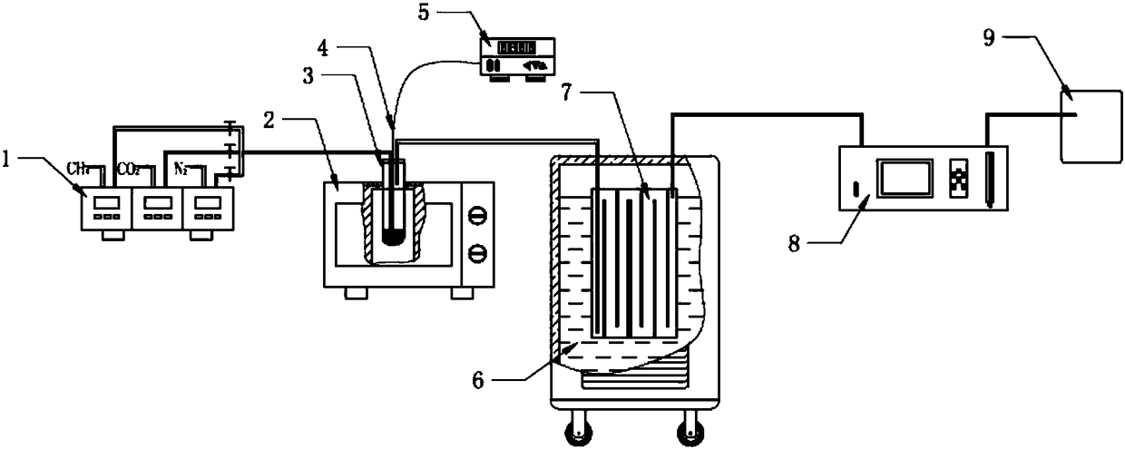
[0004] The embodiment of the present application solves the problem of insufficient combined utilization of lignite and biomass in the prior art by providing a device and method for microwave co-pyrolysis of lignite and biomass

Method used


Image

  • Device and method for lignite and biomass microwave co-pyrolysis reaction
  • Device and method for lignite and biomass microwave co-pyrolysis reaction
  • Device and method for lignite and biomass microwave co-pyrolysis reaction

Examples


Embodiment 1

[0044] After air-dried coal samples and corncobs were pulverized into <0.15mm powders, 10 g of the total mixed sample with a mass ratio of lignite to corncobs of 7:3 was prepared and transported to the quartz reactor, using microwaves as the heat source , under the microwave power of 700W, heating for 25min, the co-pyrolysis semi-coke product remains at the bottom of the quartz reactor, the oil-gas mixture is condensed by a circulating cooling device, and the pyrolysis tar and pyrolysis gas are separated, wherein the pyrolysis gas continues to Real-time analysis by online gas analyzer.

Embodiment 2

[0046] After air-dried coal samples and corncobs were pulverized to <0.15mm powders, 10 g of the total mixed sample with a mass ratio of lignite to corncobs of 8:2 was prepared and transported to a quartz reactor, using microwaves as a heat source. The microwave power is 460W, heating for 25min, the co-pyrolysis semi-coke product stays at the bottom of the quartz reactor, the oil-gas mixture is condensed by the circulating cooling device, and the pyrolysis tar and pyrolysis gas are separated, and the pyrolysis gas continues to pass through the online gas analyzer Perform real-time analysis.

Embodiment 3

[0048] After air-dried coal samples and corncobs were pulverized to <0.15mm powders, 10 g of the total mixed sample with a mass ratio of lignite to corncobs of 8:2 was prepared and transported to a quartz reactor, using microwaves as a heat source. The microwave power is 700W, heating for 15min, the co-pyrolysis semi-coke product stays at the bottom of the quartz reactor, the oil-gas mixture is condensed by the circulating cooling device, and the pyrolysis tar and pyrolysis gas are separated, and the pyrolysis gas continues to pass through the online gas analyzer Perform real-time analysis.

[0049] The result after embodiment 1, embodiment 2, embodiment 3 co-pyrolysis reaction is as shown in table 1:

[0050] Table 1

[0051]

[0052] It can be seen from Table 1 that the yield of tar products from microwave co-pyrolysis of lignite and corncobs is 10-20%, the yield of semi-coke products is about 50%, and the CO and H in the pyrolysis gas 2 and CH 4 The sum of the average...


PUM


Abstract

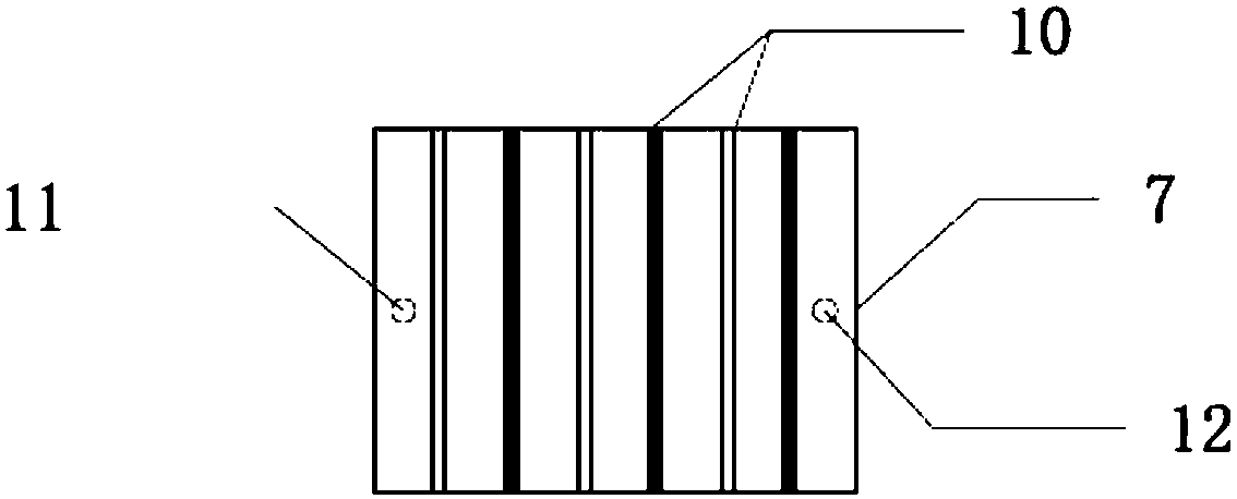
The invention belongs to the technical field of energy sources, and discloses a device and method for lignite and biomass microwave co-pyrolysis reaction. The device comprises a microwave furnace, a quartz reactor, a thermocouple, a temperature control instrument, a tar collector and a circulation cooling device. The method comprises the following steps of putting a mixed test sample for preparingthe lignite and biomass into the quartz reactor; putting the quartz reactor into a furnace cavity of the microwave furnace; inserting the thermocouple into the quartz reactor; connecting the thermocouple with the quartz reactor; starting the microwave furnace for co-pyrolysis reaction; guiding generated gas into the circulation cooling device; flowing tar products into the tar collector for storage; guiding co-pyrolysis gas into a gas collecting bag to be stored. Rest solid in the quartz reactor is semi-coke products. The problem of insufficient lignite and biomass combination utilization inthe prior art is solved. The device and the method provided by the invention have the advantages that the lignite and biomass can be cleanly and efficiently combined; mass industrial production is easily realized.

Description

technical field [0001] The invention relates to the field of energy technology, in particular to a device and method for microwave co-pyrolysis reaction of lignite and biomass. Background technique [0002] my country has rich reserves of coal resources. According to the 2017 BP World Energy Statistical Yearbook, my country's proven recoverable coal reserves are about 244 billion tons, ranking third in the world, and low-rank coal accounts for 55% of the total coal reserves. It has the characteristics of low degree of coalification, high content of humic acid, more oxygen-containing functional groups, more volatile water content, which is not suitable for long-term storage and long-distance transportation, and low calorific value of combustion, which is not suitable for being used alone as a power fuel. The low utilization rate in the process and the excessive emission of polluting gases have caused serious environmental problems, which have restricted its large-scale industri...

Claims


Application Information

Patent Timeline
IPC IPC(8): C10B53/04C10B53/02C10B23/00C10G1/00
CPCC10B23/00C10B53/02C10B53/04C10G1/00Y02E50/10
Inventor 柯萍何选明方红明刘靖冯东征赵璐涵
Owner WUHAN UNIV OF SCI & TECH
Learn More