Membrane-dispersion liquid-phase cycle hydrorefining method

A film-dispersed, liquid-phase technology, applied in hydroprocessing, refining to remove heteroatoms, petroleum industry, etc., can solve the problems of low reaction space velocity, complicated operation process, uneven dispersion, etc., and achieve easy operation and control, The effect of low reaction temperature and high operating flexibility

Active Publication Date: 2018-09-04
CNOOC TIANJIN CHEM RES & DESIGN INST +3
View PDF14 Cites 11 Cited by
  • Summary
  • Abstract
  • Description
  • Claims
  • Application Information

AI Technical Summary

Problems solved by technology

[0007] U.S. Patents US6213835, US6428686, etc. disclose a hydrogenation process for pre-dissolving hydrogen, which increases the amount of dissolved hydrogen by recycling hydrogenated oil, but it does not solve the problem of H 2 S, NH 3 The problem of removal of harmful impurities, such as harmful impurities, leads to their continuous accumulation in the reactor, which greatly reduces the reaction efficiency
[0008] Chinese patent CN 101724443A discloses a two-phase hydrogenation treatment method for distillate oil, in which raw materials, hydrogen and recycled hydrogenation products are saturated with hydrogen in a pre-saturated high-pressure tank to form a two-liquid phase mixture of raw materials / hydrogenation products / hydrogen , the hydrogen in the liquid phase mixture is separated, and the saturated dissolved hydrogen mixture passes through a single-stage or multi-stage internal cross-flow reactor, although the dissolved hydrogen and H 2 S, NH 3 and other harmful gas release problems, but the structure of the cross-flow reactor is complex, the bottom of the reactor is equipped with a cross-flow stripping zone, the volume of the reactor is large, and the operation process is complicated
In addition, the pre-mixing effect is not good, and the dispersion of gas in the oil is uneven, which affects the performance of the catalyst. Therefore, the reactor volume is large and the reaction space velocity is low.

Method used


Image

  • Membrane-dispersion liquid-phase cycle hydrorefining method
  • Membrane-dispersion liquid-phase cycle hydrorefining method
  • Membrane-dispersion liquid-phase cycle hydrorefining method

Examples


Embodiment 1

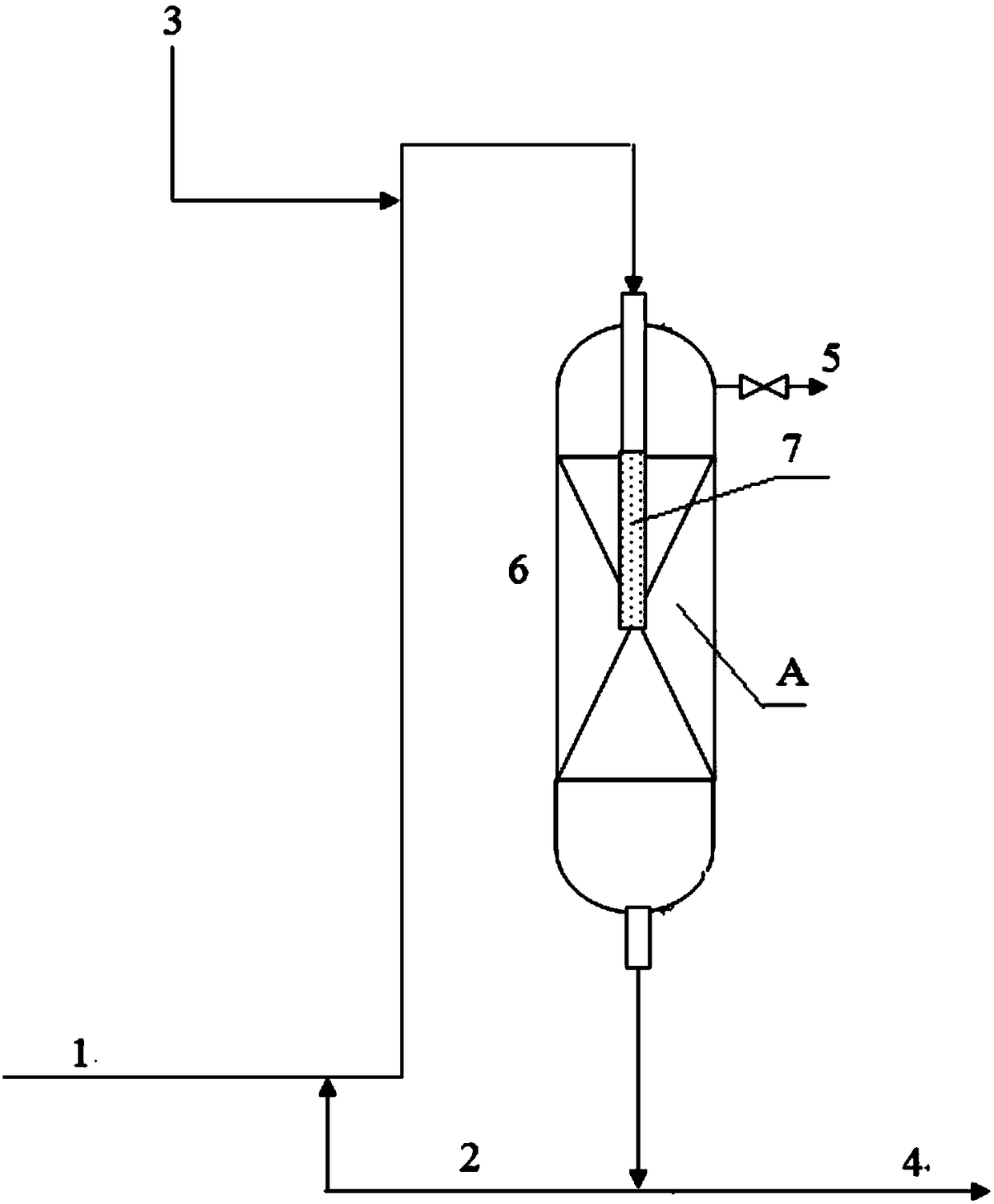
[0035] The production of clean oil products is realized by adopting the membrane-dispersed liquid-phase circulating hydrofining method of the present invention, which only includes the scheme of a single hydrogenation reactor bed, and the schematic diagram of the process flow is as follows figure 1 As shown, in this process, the length of the membrane tube goes deep into 1 / 3 of the catalyst bed. The reaction material used is the bottom feed mode, and some equipment, such as pumps and heat exchangers, are omitted in the figure, but this is well known to those of ordinary skill in the art. Such as figure 1 As shown, the detailed description of the process flow is as follows: After the distillate oil raw material 1 is mixed with the recycled product 2 at the outlet of the hydrogenation reactor 6, it is pre-saturated with hydrogen dissolved in the pipeline with the new hydrogen 3 from the new hydrogen booster. After being saturated with hydrogen, the liquid enters the hydrogenati...

Embodiment 2

[0046] Compared with embodiment 1, used fresh raw material, THDS-I hydrorefining catalyst are the same as embodiment 1. The difference in catalyst loading is that the loading volume of THDS-1 hydrorefining catalyst is 25% of that in Example 1, the hydrogenation process conditions are the same as in Table 1-2 in Example 1, and the properties of the hydrogenation reaction product refined diesel oil are shown in Table 2-1 .

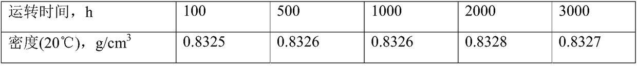
[0047] Table 2-1 Properties of refined oil produced by hydrogenation reaction

[0048] running time, h

Embodiment 3

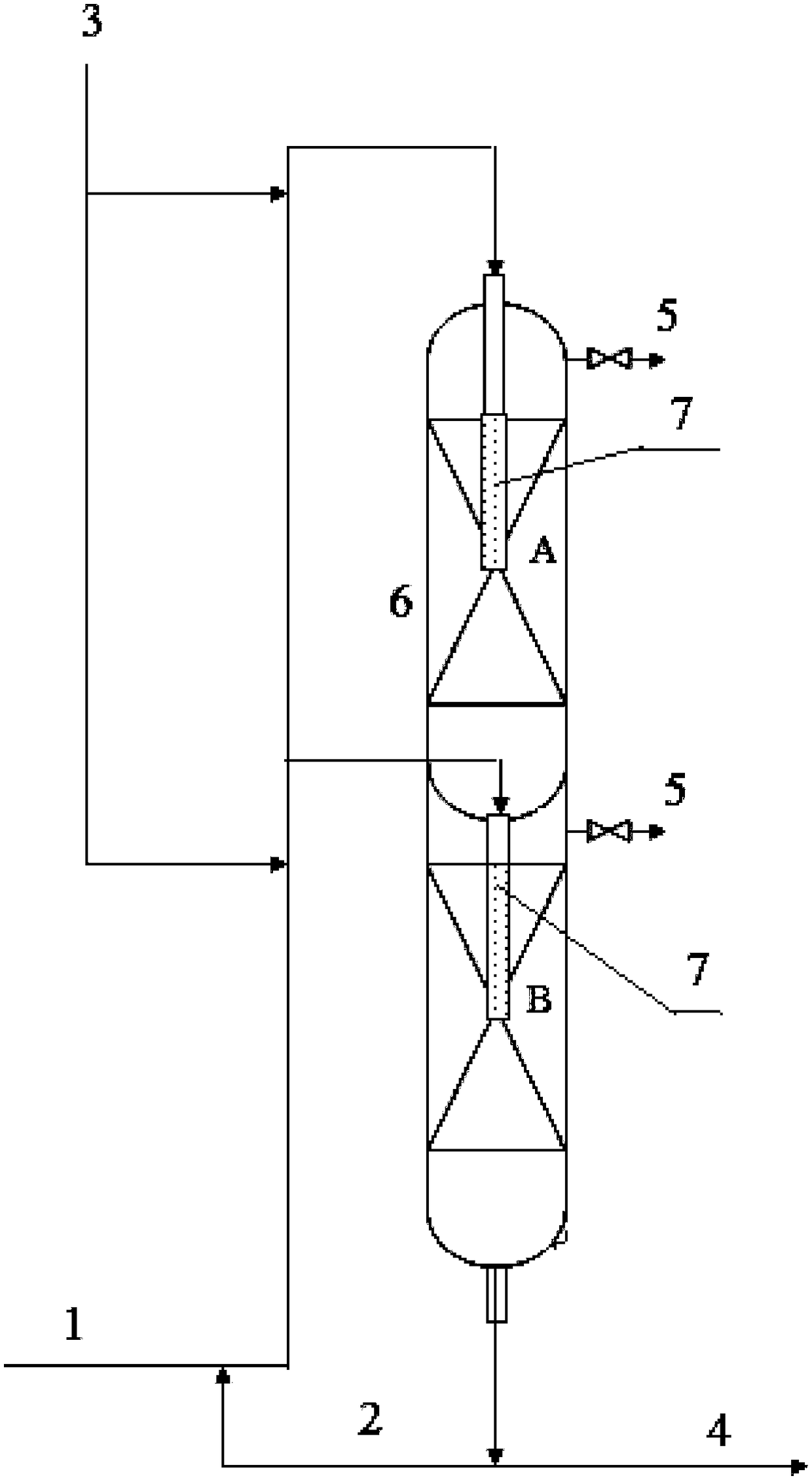
[0056] The production of clean oil products is realized by adopting the membrane-dispersed liquid-phase circulating hydrofining method of the present invention, which includes the scheme of two hydrogenation reactor beds, and the schematic diagram of the process flow is as follows figure 2 As shown, in this process, the length of the membrane tube in each reactor bed reaches 1 / 3 of the catalyst bed. The reaction material used is the bottom feed mode, and some equipment, such as pumps and heat exchangers, are omitted in the figure, but this is well known to those of ordinary skill in the art. Such as figure 2 As shown, the process flow is described in detail as follows: After the distillate oil raw material 1 is mixed with the recycled product 2 at the outlet of the hydrogenation reactor, it is pre-saturated with hydrogen dissolved in the pipeline with the new hydrogen 3 from the new hydrogen booster. After being saturated with hydrogen, the liquid raw material enters the po...


PUM

PropertyMeasurementUnit
pore sizeaaaaaaaaaa

Abstract

The invention discloses a membrane-dispersion liquid-phase cycle hydrorefining method. The membrane-dispersion liquid-phase cycle hydrorefining method comprises the following steps: performing hydrogen saturation on a distillate raw material, hydrogen and a circulating liquid hydrogenation product in a pipeline to form a liquid-phase mixture of distillate raw material/hydrogenation product/hydrogen, enabling the liquid-phase mixture with saturated dissolved hydrogen to enter a porous membrane tube for liquid-phase feed dispersion, which is arranged at an inlet of a fixed-bed hydrogenation reactor, and entering a reactor bed after membrane dispersion, wherein the reactor is filled with a hydrogenation catalyst; dispersing the liquid-phase mixture from the membrane tube, entering a catalystbed zone, performing a hydrogenation reaction, circulating a part of a reaction product from the bottom of the hydrogenation reactor, mixing with a fresh raw material, discharging a part from a reaction system and entering a subsequent product storage unit. By the membrane-dispersion liquid-phase cycle hydrorefining method, the activity of the whole catalyst can be effectively played while hydrogen mixing is achieved, the operating life of the hydrogenation catalyst is prolonged, the hydrogenation reaction efficiency is increased, and the sulfur nitrogen and aromatic hydrocarbon contents of aproduct can be further reduced.

Description

technical field [0001] The invention belongs to the field of hydrogenation refining, and in particular relates to a method for producing clean oil products through a membrane dispersion liquid phase circulation hydrogenation process. Background technique [0002] Under the situation of developing low-carbon economy, circular economy and realizing sustainable development, the pace of upgrading the quality of oil products in my country has been significantly accelerated, and the quality requirements for clean oil products are becoming more and more stringent. The production of clean oil products has become one of the key points in the development of my country's oil refining industry. Catalytic hydrogenation process is the main means of producing clean oil products, and one of the most effective methods for deep removal of impurities such as sulfur, nitrogen, oxygen and metals in distillate raw materials. At present, the most mainstream hydrogenation technology is the gas pha...

Claims


Application Information

Patent Timeline
Patent Type & Authority Applications(China)
IPC IPC(8): C10G45/02C10G65/04
CPCC10G45/02C10G65/04C10G2300/202
Inventor 南军于海斌贺胜如于群王庆波冯俊发张景成肖寒朱金剑张玉婷彭雪峰张国辉宋国良张尚强王帅耿姗
Owner CNOOC TIANJIN CHEM RES & DESIGN INST
Why Eureka
Try Eureka