Microfluid extraction expansion reactor for 3D printing and applications of microfluid extraction expansion reactor

A 3D printing and microfluidic technology, applied in the improvement of process efficiency, additive processing, etc., can solve the problems of low throughput, unrealistic, and high processing cost of microfluidic chips, achieve rapid separation, shorten time, and avoid extractants Effects of contact with air

Pending Publication Date: 2018-09-04
KUNMING UNIV OF SCI & TECH
View PDF6 Cites 5 Cited by
  • Summary
  • Abstract
  • Description
  • Claims
  • Application Information

AI Technical Summary

Problems solved by technology

[0011] In the research field of microfluidic extraction, some microchannel chips with extremely small feature sizes are often used to study the relevant condition parameters of microfluidic extraction effects. Although these chips can obtain high single-stage extraction efficiency, due to their extremely low throughput , and the processing cost of the microfluidic chip is high, it is very unrealistic to apply it in industrial production

Method used


Image

  • Microfluid extraction expansion reactor for 3D printing and applications of microfluid extraction expansion reactor
  • Microfluid extraction expansion reactor for 3D printing and applications of microfluid extraction expansion reactor
  • Microfluid extraction expansion reactor for 3D printing and applications of microfluid extraction expansion reactor

Examples


Embodiment 1

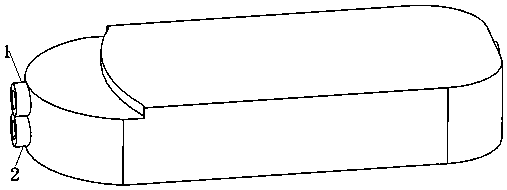
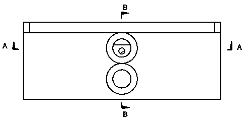
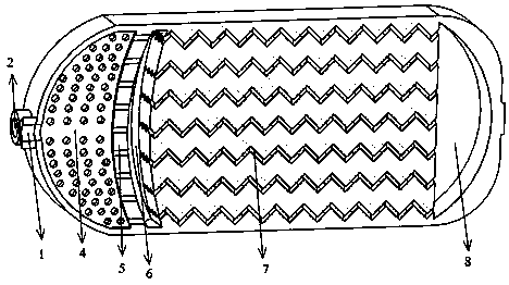
[0045] Such as Figures 1 to 6As shown in 9 and 10, the 3D printed microfluidic extraction expansion reactor includes water phase inlet 1, oil phase inlet 2, mixed liquid collection chamber I3, droplet cutting sieve plate 4, mixed liquid collection chamber partition 5, Mixed liquid collection chamber II6, mixed reaction microchannel 7, mixed liquid collection chamber III8 and mixed liquid outlet 9, one side of the microfluidic extraction expansion reactor is provided with a mixed liquid collection chamber I3 communicated with the water phase inlet 1 and connected with the oil phase The oil phase chamber connected to the inlet 2, the bottom of the mixed liquid collection chamber I3 is provided with a droplet cutting sieve plate 4, and the bottom of the mixed liquid collection chamber I3 communicates with the oil phase chamber through the droplet cutting sieve plate 4, and the side of the mixed liquid collection chamber I3 After passing through the partition plate 5 of the mixed...

Embodiment 2

[0050] The 3D printed microfluidic extraction expansion reactor in Example 1 was applied in the process of extraction, recovery of indium and separation of iron.

[0051] Such as Figure 7 As shown, the 3D printed microfluidic extraction scale-up reactor is applied in the extraction recovery of indium and separation of iron:

[0052] The sulfuric acid system solution containing 2.32g / L indium and 1.42g / L iron (using H 2 SO 4 Solution Adjust the pH value of the aqueous phase solution to 0.5) as the aqueous phase stock solution 11, and D2EHPA (dioctyl phosphate) diluted with 260# solvent oil (the volume ratio of 260# solvent oil to D2EHPA is 7:3) as the oil phase The stock solution 11 is pumped into the water phase inlet 1 and the oil phase inlet 2 of the microfluidic extraction expansion reactor 14 through the flow pump I12 and the flow pump II13 with a maximum flow rate of 100ml / min respectively (both the set flow rate is 0.6ml / min). Mix in middle, stay for 210s, then extrac...

Embodiment 3

[0054] Such as Figures 1 to 6 As shown in 9 and 10, the 3D printed microfluidic extraction expansion reactor includes water phase inlet 1, oil phase inlet 2, mixed liquid collection chamber I3, droplet cutting sieve plate 4, mixed liquid collection chamber partition 5, Mixed liquid collection chamber II6, mixed reaction microchannel 7, mixed liquid collection chamber III8 and mixed liquid outlet 9, one side of the microfluidic extraction expansion reactor is provided with a mixed liquid collection chamber I3 communicated with the water phase inlet 1 and connected with the oil phase The oil phase chamber connected to the inlet 2, the bottom of the mixed liquid collection chamber I3 is provided with a droplet cutting sieve plate 4, and the bottom of the mixed liquid collection chamber I3 communicates with the oil phase chamber through the droplet cutting sieve plate 4, and the side of the mixed liquid collection chamber I3 After passing through the partition plate 5 of the mixe...


PUM

PropertyMeasurementUnit
thicknessaaaaaaaaaa
diameteraaaaaaaaaa
lengthaaaaaaaaaa

Abstract

The invention relates to a microfluid extraction expansion reactor for 3D printing and applications of the microfluid extraction expansion reactor and belongs to the technical field of microfluid extraction. The microfluid extraction expansion reactor for 3D printing comprises a water phase inlet, an oil phase inlet, a mixed liquid collection cavity I, a liquid drop cutting sieve plate, a mixed liquid collection cavity partition, a mixed liquid collection cavity II, a mixed reaction microchannel, a mixed liquid collection cavity III and a mixed liquid outlet. The applications of the microfluidextraction expansion reactor for 3D printing comprise single-phase or multi-phase reaction microfluid extraction including a gas-liquid reaction and a liquid-liquid reaction. According to the microfluid extraction expansion reactor for 3D printing, oil-water two phase separating is rapid, the extraction reaction time is short, and an emulsifying phenomenon cannot occur.

Description

technical field [0001] The invention relates to a 3D printed microfluidic extraction expansion reactor and its application, belonging to the technical field of microfluidic extraction. Background technique [0002] In the past 20 years, as a new concept, microfluidic technology has shown its great advantages in the field of chemical engineering. At present, microreactors have been rapidly developed and applied in a wide range of fields. Although the use of microreactors does not change the reaction mechanism and intrinsic kinetic characteristics, when the two-phase fluid is in the micron scale or even smaller, their interface-to-volume ratio will increase sharply, and the concentration gradient of elements will be large. As a result, the mass transfer driving force is greatly improved. The traditional industrial extraction process requires strong stirring to enhance the mass transfer effect between the two phases, which will form a large number of water-in-oil and oil-in-wa...

Claims


Application Information

Patent Timeline
Patent Type & Authority Applications(China)
IPC IPC(8): C22B3/02C22B3/26B33Y80/00
CPCC22B3/02B33Y80/00C22B3/26Y02P10/20
Inventor 巨少华周澳李熙腾彭金辉张利波黎氏琼春田时泓王奇朱艳芳
Owner KUNMING UNIV OF SCI & TECH
Why Eureka
Try Eureka