Defogging device
A technology for defogging equipment and defogging components, which is applied in gas treatment, membrane technology, dispersed particle separation, etc., can solve the problems of complex structure of the defogger, large pressure drop of the defogger, and difficulty in manufacturing, and achieves simple structure, The effect of reducing fog entrainment and not easy to scale
Active Publication Date: 2018-09-07
CHINA PETROLEUM & CHEM CORP +1
View PDF9 Cites 0 Cited by
- Summary
- Abstract
- Description
- Claims
- Application Information
AI Technical Summary
Problems solved by technology
[0006] The demister described in CN200920128824.1 is composed of a cooler, a coarse demister and a fine demister. The disadvantage of the traditional mist eliminator is that the liquid droplets flow countercurrently to the direction of the airflow, which improves the mist removal efficiency, but the structure of the mist eliminator is complex and difficult to manufacture. easy to clog
Method used
View moreImage
Smart ImageViewing Examples

Examples
Embodiment
[0058] A wet scrubber purifies flue gas 160000Nm 3 / h, in which the apparent water concentration is 10-16g / Nm 3 , the apparent water concentration in the exhaust gas is less than 0.8g / Nm after demisting by the present invention 3 , the defogging efficiency is greater than 92%.
Login to View More PUM
 Abstract
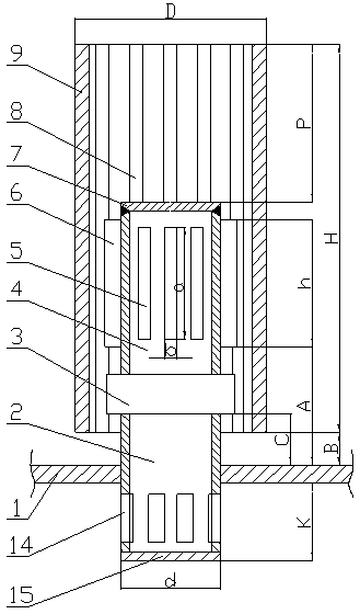
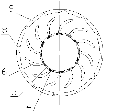
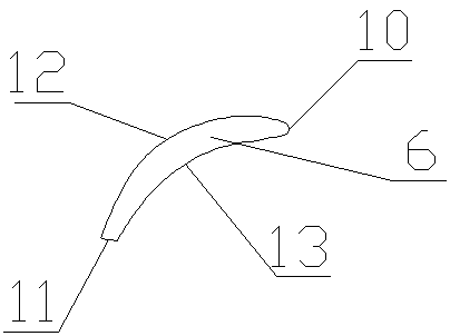
The invention discloses a defogging device. The defogging device comprises a plurality of defogging components; each defogging component comprises a gas riser pipe and an outer barrel; the outer barrel is arranged on the outer side of the gas riser pipe and located on the same axis as the gas riser pipe; the gas riser pipe is axially divided into an upper part and a lower part, the upper part is agas riser pipe I, the lower part is a gas riser pipe II, and the gas riser pipe I and the gas riser pipe II are connected with each other by a bearing; the gas riser pipe I is circumferentially provided with a plurality of slits; vanes are circumferentially arranged on the gas riser pipe I at positions close to the slits; the part, located below a tray, of the gas riser pipe II is circumferentially and uniformly provided with a plurality of gas inlets; inflow gas deflectors are arranged near the gas inlets and are connected with the inner wall of the gas riser pipe through connecting members;and each connection member consists of a baffle plate and a rotating shaft. The defogging device of the invention has the advantages of simple structure, small pressure drop, small possibility of scale formation, convenient installation, reduced mist entrainment and capacity of effectively realizing gas-liquid separation, and is especially applicable to occasions with large gas flow fluctuations.
Description
technical field [0001] The invention relates to a demisting device, which belongs to the field of gas-liquid separation in chemical engineering, and is suitable for the gas-liquid separation process in the fields of chemical engineering, environmental protection and the like. Background technique [0002] SO 2 Dust and air pollution are important causes of air pollution in my country, and they are also the key air pollutants currently under control in my country. At present, most of the wet process is used in the field of environmental protection. In the flue gas desulfurization process of the wet process, during the operation of the absorption tower, it is easy to generate "fog" with a particle size of 10-60 microns, which not only contains water, but also dissolves sulfuric acid. , sulfate, SO 2 It will pollute the atmospheric environment and cause serious corrosion to the exhaust pipe and heat exchanger. Therefore, in the wet desulfurization process, the purified gas m...
Claims
Login to View More Application Information
Patent Timeline
 IPC IPC(8): B01D45/00B01D45/06B01D45/16B01D45/08B01D45/02B01D53/26B01D53/78B01D53/50
CPCB01D45/00B01D45/02B01D45/06B01D45/08B01D45/16B01D53/26B01D53/50B01D53/78B01D2258/0283
Inventor 金平李欣王晶刘忠生刘淑鹤王海波王昊辰
Owner CHINA PETROLEUM & CHEM CORP
Features
- R&D
- Intellectual Property
- Life Sciences
- Materials
- Tech Scout
- Unparalleled Data Quality
- Higher Quality Content
- 60% Fewer Hallucinations
Learn More Browse by: Latest US Patents, China's latest patents, Technical Efficacy Thesaurus, Application Domain, Technology Topic, Popular Technical Reports.
© 2025 PatSnap. All rights reserved.Legal|Privacy policy|Modern Slavery Act Transparency Statement|Sitemap|About US| Contact US: help@patsnap.com