
Rotary demister

A demister and rotating technology, applied in chemical instruments and methods, dispersed particle separation, separation methods, etc., can solve the problems of difficult processing, high processing and manufacturing costs, complex technical structure, etc., to reduce mist entrainment, Increase the contact area and facilitate the effect of trapping

Active Publication Date: 2018-09-07
CHINA PETROLEUM & CHEM CORP +1
View PDF9 Cites 2 Cited by
  • Summary
  • Abstract
  • Description
  • Claims
  • Application Information

AI Technical Summary

Problems solved by technology

During the separation process of the liquid phase and the gas phase of this technology, gas-liquid cross flow can be realized, so the secondary entrainment effect of the gas relative to the liquid droplet is greatly reduced, but the technical structure is very complicated, the processing difficulty is relatively large, and the corresponding processing and production costs are relatively high.

Method used


Image

  • Rotary demister
  • Rotary demister
  • Rotary demister

Examples


Embodiment 1

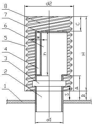
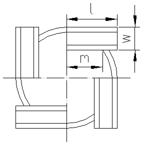
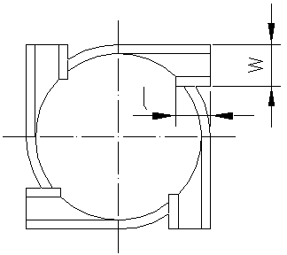
[0049] Apply the demister of the present invention to a wet scrubber to purify flue gas. The diameter of the outer cylinder of the demister assembly is 180 mm, the diameter of the air riser is 80 mm, and 4 rectifying channels are used. The length of the rectifying channel is 40 mm and the width is 20 mm. The height is 40mm, the end of the side wall II is flush with the inner wall of the air riser, the distance A between the bottom of the rectification channel and the tray is 80mm, the distance S between the bottom of the bearing and the tray is 40mm, and the distance C between the upper edge of the outer cylinder and the upper edge of the air riser is 170mm, the distance B from the lower edge of the outer cylinder to the tray is 20mm, and the total height H of the outer cylinder is 270mm; the internal thread on the outer cylinder adopts a single thread ordinary thread, the major diameter D of the thread is 177mm, the middle diameter D2 of the thread is 174mm, and the minor diame...

Embodiment 2

[0051] Apply the demister of the present invention to a wet scrubber to purify flue gas. The diameter of the outer cylinder of the demister assembly is 180 mm, the diameter of the air riser is 80 mm, and 4 rectifying channels are used. The length of the rectifying channel is 40 mm and the width is 20 mm. The height is 40mm, the end of the side wall II is flush with the inner wall of the air riser, the distance A between the bottom of the rectification channel and the tray is 80mm, the distance S between the bottom of the bearing and the tray is 40mm, and the distance C between the upper edge of the outer cylinder and the upper edge of the air riser is 170mm, the distance B from the lower edge of the outer cylinder to the tray is 20mm, and the total height H of the outer cylinder is 270mm; when the internal thread on the outer cylinder adopts five-line trapezoidal thread, the major diameter D of the thread is 177mm, the middle diameter D2 of the thread is 166mm, and the minor dia...


PUM

PropertyMeasurementUnit
heightaaaaaaaaaa
diameteraaaaaaaaaa
diameteraaaaaaaaaa

Abstract

The invention discloses a rotary demister. The rotary demister comprises a plurality of demisting components; each demisting component comprises a gas riser pipe and an outer barrel; the outer barrelis arranged on the outer side of the gas riser pipe and located on the same axis as the gas riser pipe; the inner surface of the outer barrel is of a thread structure; the gas riser pipe is axially divided into an upper part and a lower part, the upper part is a gas riser pipe I, the lower part is a gas riser pipe II, and the gas riser pipe I and the gas riser pipe II are connected with each otherby a bearing; the gas riser pipe II is fixed on a tray; and a rectification channel is arranged on the circumference of gas riser pipe I. The demister of the invention realizes the separation of droplets from gas by rectification, acceleration and scraping effect in the flowing process of fluids. The demister of the invention has the advantages of simple structure, convenient installation and small possibility of scale formation, and can effectively realize gas-liquid separation and reduce entrainment of mist.

Description

technical field [0001] The invention relates to a gas-liquid separation device, in particular to a rotary demister. Background technique [0002] A large amount of SO is produced in the production process of electric power, metallurgy, petrochemical and other industries 2 Harmful substances such as dust and dust have brought serious acid rain hazards and smog weather, and are currently the key air pollutants controlled in our country. At present, the wet desulfurization process is widely used in the field of environmental protection to remove sulfur dioxide and other harmful substances in the flue gas, that is, to spray lye on the flue gas to absorb or adsorb these harmful substances. However, in the wet desulfurization process, the flue gas after desulfurization in the absorption tower contains a large number of fine droplets with a particle size of about 10-60 microns, and sulfuric acid, sulfate, SO 2 etc., will not only pollute the atmospheric environment, but also caus...

Claims


Application Information

Patent Timeline
Patent Type & Authority Applications(China)
IPC IPC(8): B01D45/08
CPCB01D45/08
Inventor 王晶李欣刘忠生李磊刘淑鹤王海波金平韩天竹齐慧敏
Owner CHINA PETROLEUM & CHEM CORP
Learn More