Simulated imaging system based on flexible OLED display screen

An imaging system and display technology, applied in the field of simulation imaging, can solve the problems of increasing the load of the motion system of the simulator equipment, difficult to achieve full automation of system calibration, and large size of the visual field simulation system, achieving light weight, high contrast, and high system performance. low consumption effect

Pending Publication Date: 2018-09-07
中航大(天津)模拟机工程技术有限公司
View PDF10 Cites 0 Cited by
  • Summary
  • Abstract
  • Description
  • Claims
  • Application Information

AI Technical Summary

Problems solved by technology

Multiple projectors present a picture, which requires edge fusion of the projectors, which is very difficult and rarely presents a completely consistent picture after the fusion is completed; in order to maintain the brightness of the image, it is necessary to replace the light bulb frequently, usually once every six months. The bulb is around 2000RMB, and the maintenance cost is high
[0006] The traditional field of view simulation system is bulky, accounting for about half of the airborne space of the entire simulation equipment, and it is heavy, which increases the load on the movement system of the simulator equipment; system calibration such as mirror film curvature, projector screen fusion, brightness adjustment, color difference adjustment, etc. need Professional equipment, decentralized adjustment, it is difficult to achieve full automation of system calibration; projectors, visual program control equipment, mirror film controllers, etc. need long-term power supply, high energy consumption

Method used


Image

  • Simulated imaging system based on flexible OLED display screen
  • Simulated imaging system based on flexible OLED display screen
  • Simulated imaging system based on flexible OLED display screen

Examples


Embodiment Construction

[0019] Embodiments of the present invention are described in further detail below in conjunction with the accompanying drawings:

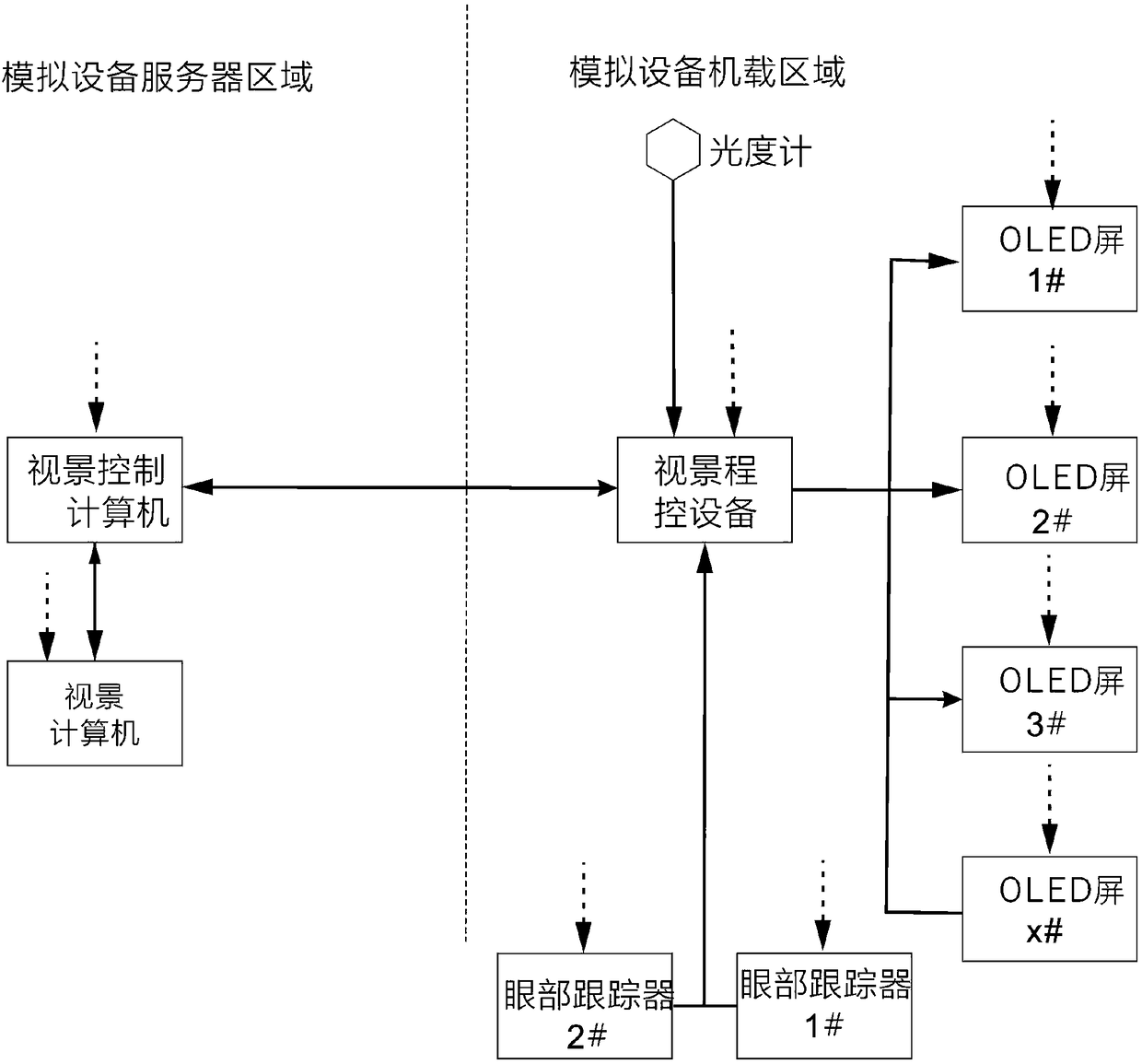
[0020] A simulation imaging system based on a flexible OLED display, such as figure 1 As shown, it includes a visual computer, a visual control computer, a visual program control device, and a plurality of flexible OLED display screens; wherein, the dotted line represents a power line, and the solid line represents a signal line; the visual computer is connected to the visual control computer , the visual computer is used to generate real-time visual pictures, and the visual control computer is used to perform final imaging adjustment and control on the real-time visual pictures generated by the visual computer, such as picture distribution, color difference adjustment, brightness adjustment and visual imaging switching functions Wait. The view control computer is respectively connected to a plurality of flexible OLED display screens through the ...


PUM


Abstract

The invention relates to a simulated imaging system based on flexible OLED display screens. The simulated imaging system is technically characterized by comprising a vision computer, a vision controlcomputer, a vision program-controlled device and multiple OLED display screens. The vision control computer is connected with the vision computer and is used for controlling on and off of the vision computer and adjusting parameters. The vision computer is connected with the multiple display screens through the vision program-controlled device and used for calling vision information of the physical position where a simulator is located from a global vision database, vison images are output to the vision program-controlled device, then the vision program-controlled device allocates the vision information output by the vision computer to different OLED display screens through network decoding. The simulated imaging system is simple in structure, small in size, light in weight and capable ofremarkably reducing the production cost.

Description

technical field [0001] The invention belongs to the technical field of simulation imaging, and relates to a flexible OLED display, in particular to a simulation imaging system based on a flexible OLED display. Background technique [0002] At present, with the advancement of microelectronics technology, simulation imaging is developing rapidly, and various simulation imaging technologies such as VR simulation interaction, holographic projection, 3D imaging, and simulation imaging have emerged. This kind of technology is mainly used in the field of aerospace simulation, ship simulation, train simulation, automobile simulation, military simulation and high-end equipment simulation, providing the simulation equipment users with a realistic and dynamic external view of the world environment, such as the vision of an aircraft simulator , ship simulator vision, train driving simulator vision, etc. [0003] Traditional simulation imaging systems such as image 3 As shown, it is ma...

Claims


Application Information

Patent Timeline
Patent Type & Authority Applications(China)
IPC IPC(8): G09G3/3208
CPCG09G3/3208
Inventor 张学杨升杜超王津京巩雨旺李侃宋长德高冰李松吕秀宾余建权王迪
Owner 中航大(天津)模拟机工程技术有限公司
Why Eureka
Try Eureka