DC power supply micro-current starting circuit

A start-up circuit and DC power supply technology, applied in the direction of electrical components, output power conversion devices, etc., can solve the problems of occupying PCB boards, large losses, increased costs, etc., achieve simple structure, use fewer components, and avoid overheating and burning bad effect

Pending Publication Date: 2018-09-07
上海希形科技有限公司
View PDF2 Cites 2 Cited by
  • Summary
  • Abstract
  • Description
  • Claims
  • Application Information

AI Technical Summary

Problems solved by technology

[0003] However, the traditional method of series current-limiting resistors cannot cut off the current-limiting resistor circuit when the power converter is working normally, so it will cause serious heat generation when the resistor value is selected to be small, and even the resistor is burned out, and the loss is also large or limited. If the resistance value of the current resistance is selected too large, it will not be able to meet the starting current required by the control chip to start.
[0004] For the shortcoming of the series current limiting resistor, the existing method is to add a switch (semiconductor switching tube) on the basis of the series current limiting resistor, and cut off the circuit of the current limiting resistor when the power converter is started; The device will increase a lot of cost and occupy a large area of ​​the PCB board

Method used


Image

  • DC power supply micro-current starting circuit
  • DC power supply micro-current starting circuit
  • DC power supply micro-current starting circuit

Examples


Embodiment 1

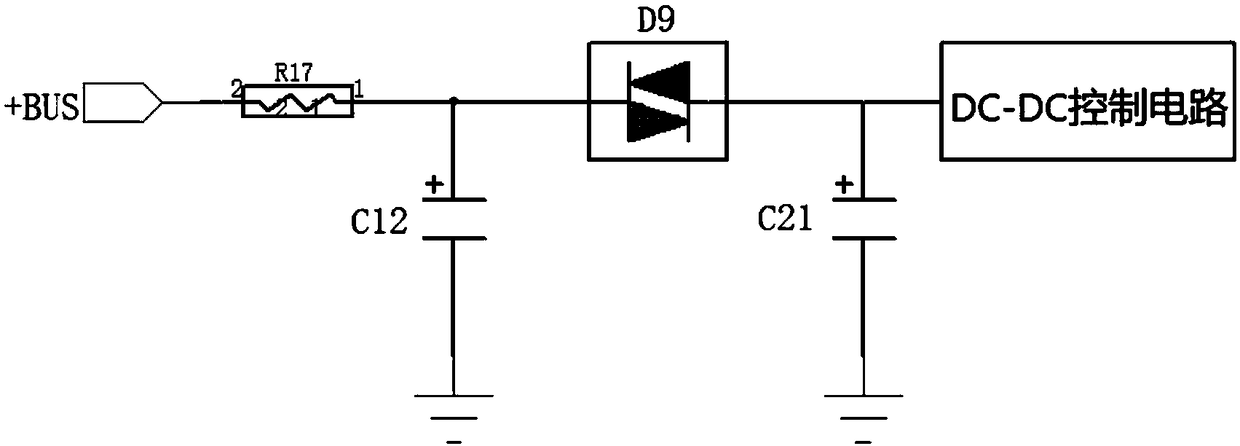
[0040] Such as figure 2 As shown, the DC power supply micro-current starting circuit provided by the present invention further includes a capacitor C21; the current limiting circuit includes a resistor R17, the tank circuit includes a capacitor C12, and the negative resistive switch includes a bidirectional trigger diode D9. One end of the resistor R17 forms a high-voltage DC power supply +BUS connection, the other end of the resistor R17 is connected to one end of the capacitor C12 and one end of the bidirectional trigger diode D9; the other end of the capacitor C12 is grounded; the other end of the bidirectional trigger diode D9 is connected to the capacitor One end of C21 forms a DC-DC control circuit connection end; the other end of capacitor C21 is grounded.

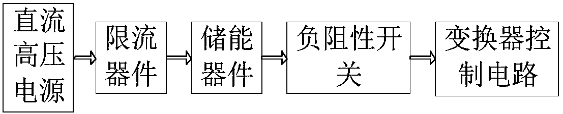
[0041] +BUS is the bus power supply of the DC converter, resistor R17 is used to limit current, C12 is used as energy storage capacitor, and the two-way trigger diode D9 is a negative resistive switch; when the DC powe...

Embodiment 2

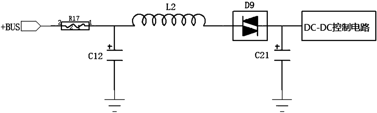
[0043] In this embodiment, an inductor L2 is added to the structure of Embodiment 1. Such as image 3 As shown, one end of the inductor L2 is connected to one end of the resistor R17 and the capacitor C12 respectively, and the other end of the inductor L2 is connected to one end of the bidirectional trigger diode D9. The inductance L2 is used to increase the Q value of the circuit when the two-way trigger diode D9 is turned on and to suppress the current rise speed, so that the current at the trigger time will not be too large and the two-way trigger diode D9 will be burned out, and the current is smoother. The impact of each device will also be greatly reduced.

Embodiment 3

[0045] In this embodiment, a Zener diode ZD1 is added to the structure of Embodiment 2. Such as Figure 4 As shown, one end of the Zener diode ZD1 is respectively connected to the other end of the resistor R17, one end of the capacitor C12, and one end of the inductor L2, and the other end of the Zener diode ZD1 is grounded. The zener diode ZD1 is used to make the two-way trigger diode D9 lose the trigger condition after the converter starts successfully, so as to protect the two-way trigger diode D9, and also can protect the energy storage capacitor.


PUM


Abstract

The invention provides a DC power supply micro-current starting circuit, comprising a current-limiting circuit, an energy storage circuit and a negative resistance switch. The current-limiting circuitlimits the current of a high-voltage DC power supply to obtain a micro current. The energy storage circuit stores the micro current. The negative resistance switch is switched on when the voltage inthe energy storage circuit reaches a set value, and is switched off when the current flowing through the negative resistance switch is lower than the holding current of the negative resistance switch.The DC power supply micro-current starting circuit which is formed by connecting the current-limiting resistor, the energy storage capacitor and the negative resistance switch in series, is simple instructure, uses fewer components, and generates loss only when a DC power converter is started.

Description

Technical field [0001] The invention relates to a starting circuit, in particular to a direct current power supply micro-current starting circuit. Background technique [0002] When the DC power converter is started, because the control circuit uses low voltage (usually within DC20V), and the input voltage of the power supply is generally above AC220V, an auxiliary winding is generally added to the transformer of the power converter. After the power supply is started, the control circuit is generally powered by the auxiliary winding, but the auxiliary winding of the transformer has no voltage output when the power converter is started, so many traditional power converters connect a current-limiting resistor in series to the DC high-voltage power supply. The control circuit can be powered by the current limiting resistor at the moment the converter starts. [0003] However, the traditional method of series current-limiting resistors cannot cut off the current-limiting resistor circ...

Claims


Application Information

Patent Timeline
Patent Type & Authority Applications(China)
IPC IPC(8): H02M1/36H02M1/32
CPCH02M1/32H02M1/36H02M1/322
Inventor 张宁
Owner 上海希形科技有限公司
Why Eureka
Try Eureka