
Sintering furnace used on solar battery production line

A technology for solar cells and production lines, applied in the field of sintering furnaces, can solve the problems affecting the photoelectric conversion efficiency of cells, poor sintering quality, and silicon wafer drift and collision, so as to achieve flexible and convenient adjustment of exhaust volume, improve product quality, and reduce pollution Effect

Inactive Publication Date: 2018-09-11
ZHANGJIAGANG GUOLONG SOLAR TECH CO LTD
View PDF0 Cites 1 Cited by
  • Summary
  • Abstract
  • Description
  • Claims
  • Application Information

AI Technical Summary

Problems solved by technology

[0002] In the current production process of solar cells, the sintering process is a crucial link. The quality of sintering directly affects the photoelectric conversion efficiency of the battery. The fill factor of the battery with high-quality sintering process can reach 78, and the conversion efficiency can exceed 17. %, but the sintering quality is not good, and the cell efficiency drops by at least 3 percentage points
In the existing sintering process, in order to improve the sintering effect, the slurry on the surface of the cell will be dried before sintering. Drying is generally done by blowing hot air. However, the hot air will cause the flow of the slurry and affect the product yield. ; and the airflow in the sintering furnace is generally blown from bottom to top, which is easy to form upward buoyancy, causing the silicon wafer to drift and collide, reducing the production quality

Method used


Image

  • Sintering furnace used on solar battery production line
  • Sintering furnace used on solar battery production line
  • Sintering furnace used on solar battery production line

Examples


Embodiment Construction

[0020] The following will clearly and completely describe the technical solutions in the embodiments of the present invention with reference to the accompanying drawings in the embodiments of the present invention. Obviously, the described embodiments are only some, not all, embodiments of the present invention. Based on the embodiments of the present invention, all other embodiments obtained by persons of ordinary skill in the art without making creative efforts belong to the protection scope of the present invention.

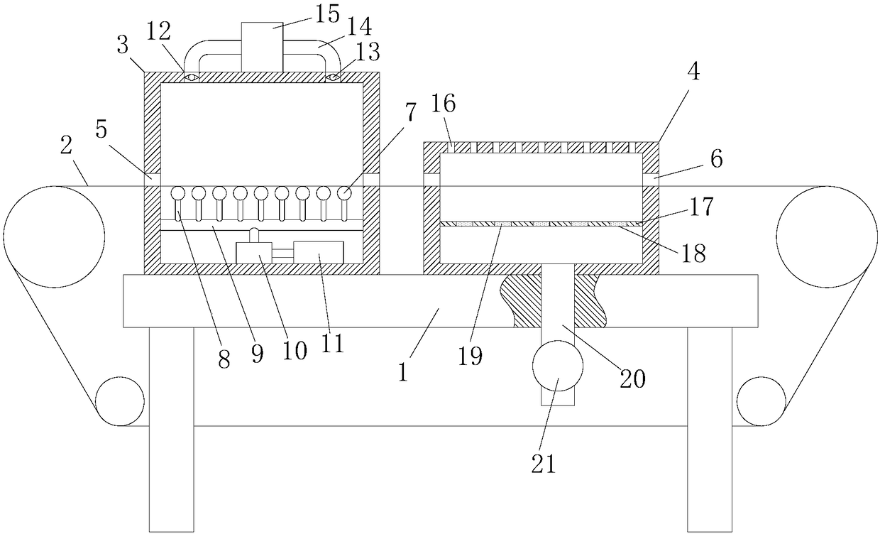
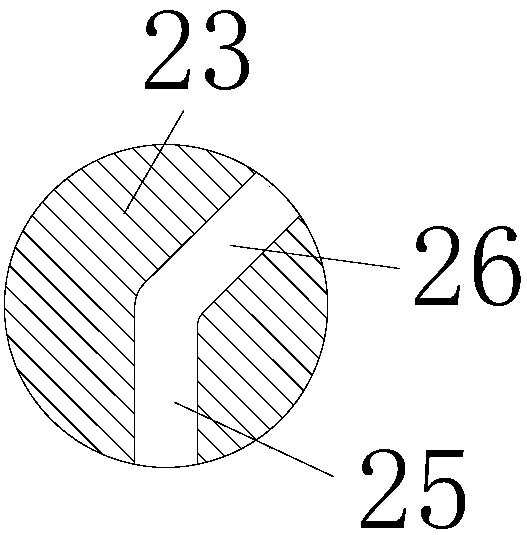
[0021] see Figure 1~4 , the present invention provides a technical solution: a sintering furnace used on a solar cell production line, including a frame 1 and a conveyor belt 2, a drying chamber 3 is provided on the left side of the top of the frame 1, and the drying chamber 3. A sintering chamber 4 is provided on the right side. The upper belt surface of the conveyor belt 2 runs through the drying chamber 3 and the sintering chamber 4. A material inlet and ...


PUM


Abstract

The invention discloses a sintering furnace used on a solar battery production line. The sintering furnace comprises a rack and a conveyor belt, wherein a drying room is arranged on the left side of the top end of the rack; a sintering room is arranged on the right side of the drying room; the upper conveyor belt surface of the conveyor belt penetrates through the drying room and the sintering room; first material inlets / outlets corresponding to the conveyor belt are formed in the left and right end side walls of the drying room; second material inlets / outlets corresponding to the conveyor belt are formed in the left and right end side walls of the sintering room; and a plurality of uniformly arranged drying devices are arranged in the drying room, the drying devices are arranged at the bottom ends of the upper conveyor belt surface of the conveyor belt, a plurality of symmetrically distributed exhaust ports are formed in the top end of the drying room, and an exhaust fan is arranged in each exhaust port. The sintering furnace disclosed by the invention reduces the influence of an air flow on a silicon wafer, prevents drifting collision of the silicon wafer as a result of blowing of the air flow, improves the product quality, can adjust the gas displacement flexibly and conveniently, and saves energy.

Description

technical field [0001] The invention relates to the technical field of solar cell production equipment, in particular to a sintering furnace used in a solar cell production line. Background technique [0002] In the current production process of solar cells, the sintering process is a crucial link. The quality of sintering directly affects the photoelectric conversion efficiency of the battery. The fill factor of the battery with high-quality sintering process can reach 78, and the conversion efficiency can exceed 17. %, but the sintering quality is not good, and the battery efficiency drops by at least 3 percentage points. In the existing sintering process, in order to improve the sintering effect, before sintering, the slurry on the surface of the cell will be dried first. Drying is generally done by blowing hot air. However, the hot air will cause the flow of the slurry and affect the product yield. ; and the airflow in the sintering furnace generally blows from bottom t...

Claims


Application Information

Patent Timeline
IPC IPC(8): F26B15/18F26B23/06F26B25/00F27B9/24H01L31/18
CPCF26B15/18F26B23/06F26B25/007F27B9/24F27M2003/025F27M2003/04H01L31/18Y02P70/50
Inventor 张文陈志运田小江李晴张华
Owner ZHANGJIAGANG GUOLONG SOLAR TECH CO LTD
Learn More