
Eureka
For R&D, Eureka makes reading and utilizing patents & technical documents easy.
Eureka AIR
Designed for self-driven R&D workflows. Generate viable solutions, solve complex R&D challenges, empower your innovation with AI.

Eureka Materials
Designed for material experts only. Revolutionize your material R&D, from search, analyze, to developing new materials.

TechResearch
Generate reliable direction feasibility study reports for your R&D in just a few steps.

TechSeek
Discover and master advanced knowledge NOW. Basics, ideas, possibilities, all at once.

TechMind
As an expert in R&D Theories, TechMind can generates customized viable solutions instantly.

TechRisk
Analyze your overall solution with one click, know your potential R&D risks in advance.

TechMonitor
Get weekly tech updates, stay abreast of the latest tech innovations and key insights.
Crankshaft polishing machine
A polishing machine and crankshaft technology, applied in grinding/polishing equipment, grinding frame, grinding machine parts, etc., can solve the problem of waste chips splashing to the center drilling, affecting the grinding effect, etc., to reduce clamping times, improve grinding efficiency, save time
- Summary
- Abstract
- Description
- Claims
- Application Information
AI Technical Summary
Problems solved by technology
Method used
Image

Examples
Embodiment Construction
[0017] The following is further described in detail through specific implementation methods:
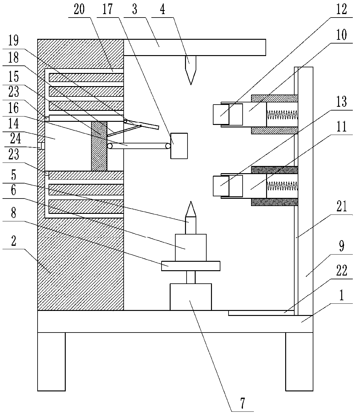
[0018] The reference signs in the drawings of the description include: workbench 1, column 2, beam 3, first thimble 4, second thimble 5, motor 6, cylinder 7, support platform 8, support rod 9, first support rod 10, The second pole 11, the first grinding wheel 12, the second grinding wheel 13, the sliding hole 14, the slider 15, the connecting rod 16, the splint 17, the ejector rod 18, the push plate 19, the blowing hole 20, the vertical groove 21, the sliding Groove 22, first one-way valve 23, second one-way valve 24.
[0019] Such as figure 1 As shown, a crankshaft polishing machine includes a workbench 1, a column 2 is installed on the left side of the workbench 1, a horizontal beam 3 is installed on the upper part of the column 2, a first thimble 4 is installed on the upper middle of the beam 3 through a bearing, and the workbench 1 There is a cylinder 7 with the piston rod arra...
PUM
 Abstract
Description
Claims
Application Information
 - R&D Engineer
- R&D Manager
- IP Professional
- Industry Leading Data Capabilities
- Powerful AI technology
- Patent DNA Extraction
Browse by: Latest US Patents, China's latest patents, Technical Efficacy Thesaurus, Application Domain, Technology Topic, Popular Technical Reports.
© 2024 PatSnap. All rights reserved.Legal|Privacy policy|Modern Slavery Act Transparency Statement|Sitemap|About US| Contact US: help@patsnap.com