Eureka AIR delivers breakthrough ideas for toughest innovation challenges, trusted by R&D personnel around the world.

Electrospinning material receiving device and manufacturing device for electrospinning

A receiving device and electrospinning technology, applied in the field of spinning manufacturing, can solve problems such as restricting cell migration and penetration, and achieve the effects of easy rotation control, avoiding uneven distribution of fibers, and reasonable overall structure

Active Publication Date: 2018-09-14
SUN YAT SEN UNIV
View PDF9 Cites 2 Cited by
  • Summary
  • Abstract
  • Description
  • Claims
  • Application Information

AI Technical Summary

Problems solved by technology

[0004] However, conventional electrospinning uses a planar receiver plate, and the resulting nanofibers are tightly packed and highly compressed, with major pore sizes of only 1 to 2 μm and a material thickness of no more than 500 μm.
Although the compact two-dimensional nanofibers are conducive to cell dispersion, they limit the migration and penetration of cells into the interior of the material.

Method used


Image

  • Electrospinning material receiving device and manufacturing device for electrospinning
  • Electrospinning material receiving device and manufacturing device for electrospinning
  • Electrospinning material receiving device and manufacturing device for electrospinning

Examples


no. 1 example

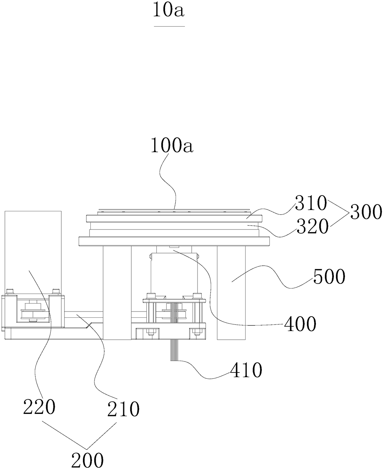
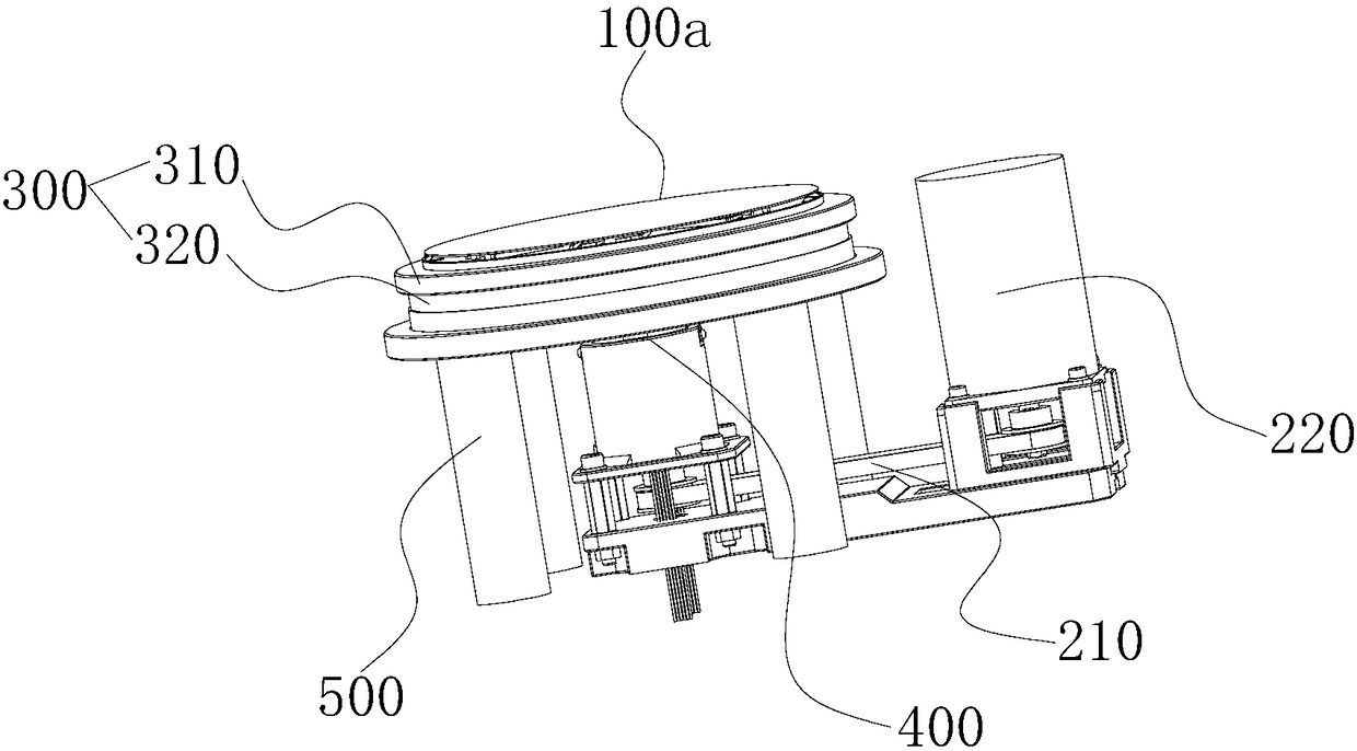
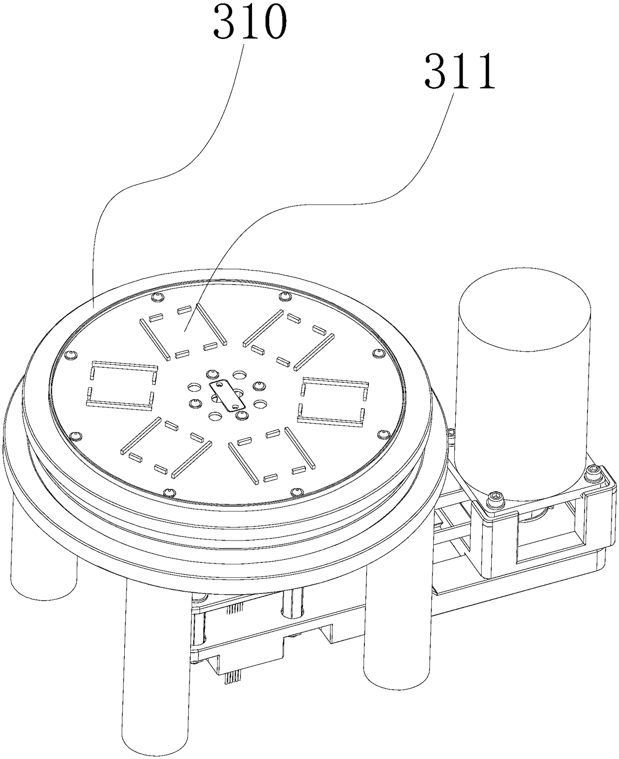
[0028] See attached figure 1 And figure 2 This embodiment provides an electrospinning material receiving device 10a, which includes: a receiving plate 100a, a driving device 200 for driving the receiving plate 100 to rotate, and a refrigerating device for cooling the receiving plate 110.

[0029] The receiving plate 100a rotates under the driving of the driving device 200, so that it can uniformly receive the fibers ejected from the nozzles in different directions at the same time, realize bi-component or multi-component electrostatic spinning, and avoid fiber distribution due to the same kind of charge repulsion. Evenly. At the same time, the receiving plate 100a is cooled by the refrigerating device, so that the surface of the receiving plate 100a is low temperature, which in turn causes the water vapor in the air to condense during the spinning process to form ice crystals, which are used as porogens and supporting materials to make the electrospun fiber vertical Direction st...

no. 2 example

[0046] See attached Figure 5 An electrospinning material receiving device 10b improved in this embodiment, the receiving plate 100b is a hollow structure with a refrigerating cavity inside, and the transmission mechanism 210 is connected to the receiving plate through a hydroelectric hybrid conductive slip ring 400. The water interface of the ring 400 is connected to the refrigeration cavity. In this embodiment, the structure of the receiving plate 100 refers to the structure of the heat dissipation plate 300 in the first embodiment, and other structures refer to the first embodiment. That is, compared with the first embodiment, this embodiment removes the In this embodiment, the upper surface of the first heat dissipation plate 310 in the first embodiment is set as a smooth surface as the receiving surface. In this embodiment, liquid nitrogen is directly introduced into the refrigeration cavity through an external refrigeration cycle system for refrigeration operation, so th...


PUM


Abstract

The invention discloses an electrospinning material receiving device and a manufacturing device for electrospinning. The electrospinning material receiving device comprises a flat receiving plate, a driving device for driving the flat receiving plate to rotate and a refrigerating device for refrigerating the flat receiving plate, wherein the driving device comprises a transmission mechanism and amotor, the power output end of the transmission mechanism is connected with the flat receiving plate, and the refrigerating device is connected to the flat receiving plate. The refrigerating device can refrigerate the flat receiving plate, so that ice crystals formed by condensing steam in air constantly grow in the spinning process and serve as a pore-foaming agent and a supporting material, anda spongy three-dimensional electrospinning material provided with communicated pores. The flat receiving plate can simultaneously and uniformly receive fiber sprayed from spraying heads in different directions under rotation, double-component or multi-component electrospinning is achieved, and ununiform fiber distribution caused by repulsion of the same electric charges is avoided.

Description

Technical field [0001] The invention relates to the field of spinning manufacturing, in particular to an electrospinning material receiving device and electrospinning manufacturing equipment. Background technique [0002] In recent years, nanotechnology has become a research frontier and research hotspot in the scientific community. Electrospinning is an important method for preparing nanofibers. It was first proposed by Fomhals in 1934. Electrospinning is a spinning process that uses electrostatic force to process polymers. Its principle is to use a high-voltage power supply to charge a melt or polymer solution to overcome surface tension and continuously spray to prepare nanofibers. [0003] The processing range of electrospinning technology covers almost all natural materials and synthetic materials, even proteins, polysaccharides, nucleic acids and biologically active substances, which are widely used in materials science, biotechnology, tissue engineering, environmental prote...

Claims


Application Information

Patent Timeline
IPC IPC(8): D01D5/00D01D11/00
CPCD01D5/0069D01D5/0076D01D5/0092D01D11/00
Inventor 全大萍杜钊夷陈诗浩郭少成曾晨光杨习锋孟月吴泽佳
Owner SUN YAT SEN UNIV
Why Eureka
Eureka Blog
Learn More