Eureka AIR delivers breakthrough ideas for toughest innovation challenges, trusted by R&D personnel around the world.

Automatic pipe arrangement system for land drill rig racking platform

A two-story platform and drilling rig technology, applied in the direction of drill pipe, drill pipe, casing, etc., can solve the problems of poor safety in the working environment, labor-intensive, low drilling efficiency, etc., achieve high stability and automation, and reduce labor intensity , The effect of improving drilling efficiency

Pending Publication Date: 2018-09-14
XI'AN PETROLEUM UNIVERSITY
View PDF6 Cites 9 Cited by
  • Summary
  • Abstract
  • Description
  • Claims
  • Application Information

AI Technical Summary

Problems solved by technology

The drill pipe discharge operation requires the cooperation of multiple people. When tripping, the drilling staff (driller, derrick and driller) must cooperate closely. Any operation error by one person may cause other personnel to be injured.
In addition, the second floor platform is about 26.5 meters away from the well platform, so the safety of derrick workers working at heights cannot be guaranteed
It can be seen that in the traditional drilling work, the working environment is not safe, the work is tedious and labor-intensive, and the drilling efficiency is not high
[0003] At present, the automatic piping system is relatively mature in the application of offshore oil drilling platforms. Due to the large size of the automatic piping system used on offshore platforms, it is not suitable for the K-type derrick commonly used on land drilling platforms, and the cost is high. less equipped

Method used


Image

  • Automatic pipe arrangement system for land drill rig racking platform
  • Automatic pipe arrangement system for land drill rig racking platform
  • Automatic pipe arrangement system for land drill rig racking platform

Examples


Embodiment Construction

[0026] The present invention will be described in detail below with reference to the accompanying drawings.

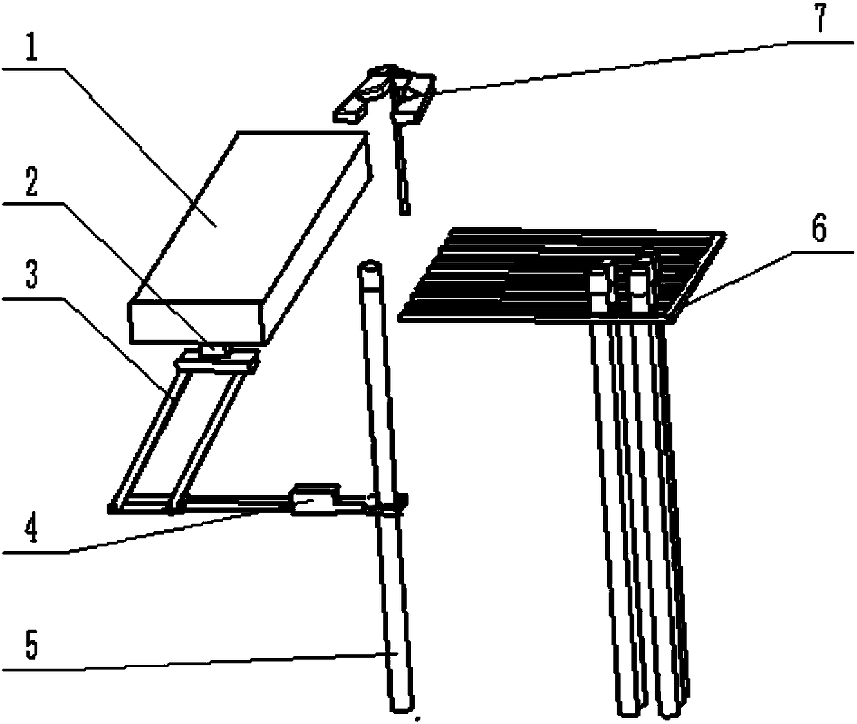
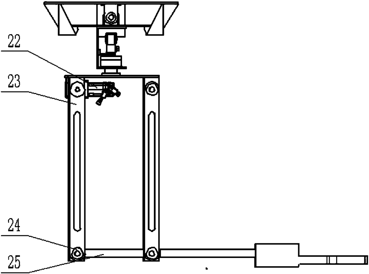
[0027] Such as figure 1 As shown: the automatic piping system of the two-story platform includes a translation mechanism 1, a rotation mechanism 2, a parallelogram mechanism 3 and a clamping mechanism 4. The parallel mechanism 1 is located above the rotation mechanism 2, and the rotation mechanism 2 and the guide rail 8 inside the parallel mechanism 1 The installed slide block 9 is connected by bolts; the shaft seat 17 of the rotating mechanism 3 is connected with the fixed upper plate 19 of the parallelogram mechanism 3; the lower connecting plate 25 on the parallelogram mechanism 3 is connected with the clamping mechanism 4.

[0028] The translation mechanism 1 is composed of a guide rail 8 and a slider 9 .

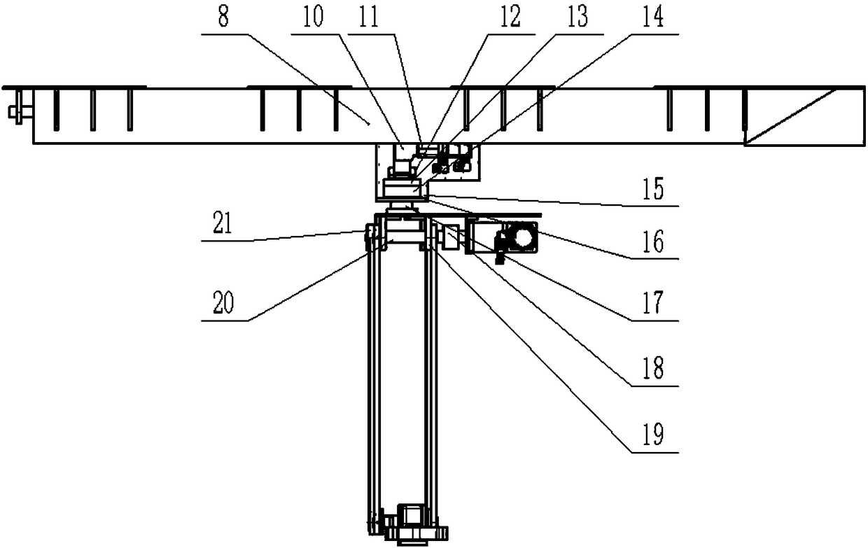
[0029] Such as figure 2 As shown: the rotating mechanism 2 is composed of a fixed casing 15, an explosion-proof motor 11, a reducer 10, a rotating shaft 17, ...


PUM


Abstract

An automatic pipe arrangement system for a land drill rig racking platform comprises a racking platform manipulator mounted on the racking platform and a drill floor auxiliary manipulator mounted on adrill floor. The racking platform manipulator comprises a transverse-moving mechanism; the transverse-moving mechanism comprises a guide rail and a sliding block, and the sliding block is mounted onthe guide rail and connected with a rotating mechanism through a bolt; the rotating mechanism is connected with a parallelogram mechanism, and a clamping mechanism used for clamping drill pipes is arranged on the parallelogram mechanism and feeds the drill pipes located on a stand arrangement frame into an elevator; the transverse-moving mechanism is located on the upper portion of the rotating mechanism, and the parallelogram mechanism operates along the guide rail and transforms the angle through the rotating mechanism; and the drill floor auxiliary manipulator used for conveying the drill pipes is arranged below the elevator. The automatic pipe arrangement system has the main effects that reciprocating moving of the drill pipes from a racking platform finger board to the wellhead centeris completed, safe and efficient work can be conducted according to a preset program, thus operators are disengaged from burdensome physical labor, the operation efficiency is improved, and automation of a drill rig is achieved.

Description

technical field [0001] The invention relates to the technical field of piping arrangement for a second-floor platform of a petroleum machinery land drilling rig, in particular to an automatic piping system for a second-story platform of a land drilling rig. Background technique [0002] In the process of oil drilling, the vertical root needs to be continuously stored or removed from the second-floor platform finger beam frame. Every time a stand is lifted, the drill pipe needs to be moved from the wellhead position to the drill pipe stand box. Each time a stand is lowered, the drill pipe needs to be moved from the stand box to the wellhead location. This process is repeated often. The whole process requires the derrick worker to extend the manipulator on the second floor platform to the center of the wellhead to connect the vertical root to the traveling block (or remove it), and the platform driller is also required to perform make-up and breakout operations. The drill p...

Claims


Application Information

Patent Timeline
Patent Type & Authority Applications(China)
IPC IPC(8): E21B19/14
CPCE21B19/14
Inventor 鲍泽富胡广珊赵均强王艳梅王冲陈少成
Owner XI'AN PETROLEUM UNIVERSITY
Why Eureka
Eureka Blog
Learn More