Method for measuring dislocation density of steel through electron back-scattered diffraction (EBSD)

A density and dislocation technology, applied in the field of steel centerline defect testing, can solve problems such as unintuitive, cumbersome process, large sample size, etc., and achieve the effect of accurate and reliable results, simplified process, fast and convenient comparison

Active Publication Date: 2018-09-14
CENT IRON & STEEL RES INST +1
View PDF7 Cites 4 Cited by
  • Summary
  • Abstract
  • Description
  • Claims
  • Application Information

AI Technical Summary

Problems solved by technology

The size of the sample used in this method is relatively large, and the measurement results can basically reflect the macroscopic distribution of dislocation density inside the sample. However, this method also needs to measure the magnetic properties of the sample such as magnetic susceptibility and coercive force. The process of obtaining the dislocation density is cumbersome and not intuitive

Method used


Image

  • Method for measuring dislocation density of steel through electron back-scattered diffraction (EBSD)
  • Method for measuring dislocation density of steel through electron back-scattered diffraction (EBSD)
  • Method for measuring dislocation density of steel through electron back-scattered diffraction (EBSD)

Examples


Embodiment approach 1

[0034] In Embodiment 1, the steel used is a low-alloy high-strength steel designed with different microalloy elements, smelted, forged, controlled rolling and controlled cooling, and then laminarly cooled to about 400°C, and then air-cooled to room temperature. There are 6 steel types in total. When there are many test samples (more than two), one of the samples can be selected as the standard sample, and the remaining samples can be used as the samples to be tested. In this implementation case, one of the samples is randomly selected as a standard sample, and the rest are used as test samples. The specific implementation method steps of Embodiment 1 are as follows:

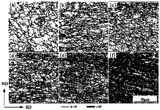
[0035] (1) Sample preparation: use wire cutting to cut a square sheet-shaped sample with a size of 7mm (length) × 7mm (width) × 3mm (thickness), and mark 6 samples of different steel types as (a)~ (f), wherein randomly selected sample (d) is a standard sample, (a), (b), (c), (e), (f) are test samples, and all sa...

Embodiment approach 2

[0042] The specific implementation method steps of the second embodiment are as follows:

[0043] In the second embodiment of the present invention, the alloy composition and production process of the sample to be tested are different from the sample in the first embodiment. The main difference is that the alloy composition is subjected to quenching heat treatment after controlled rolling, and the quenching medium is different. They are oil, water, salt water, and ice salt water respectively, and the cooling capacity is increased sequentially. The tested sample is low-alloy high-strength steel containing Cu. The post-rolling heat treatment processes are: (a) 900℃×1h+oil cooling, (b) 900℃ ℃×1h+water cooling, (c)900℃×1h+brine cooling, (d)900℃×1h+ice brine cooling.

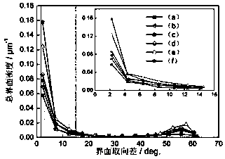
[0044] The sample of the second embodiment is carried out as steps (1) to (4) in the first embodiment, and the interface diagram after EBSD scanning is as follows Figure 5 As shown in , it can be seen that the smal...


PUM


Abstract

Disclosed is a method for measuring dislocation density of steel through the electron back-scattered diffraction (EBSD). The method includes preparing standard samples and a plurality of to-be-testedsamples, sequentially placing the samples in an scanning electron microscope with the EBSD, scanning the samples and recording scanning data, processing the scanning data, determining interfacial density Pi(standard) of small-angle interface of the standard sample and interfacial density Pi of small-angle interface of the to-be-tested samples, measuring dislocation density d (standard) of the standard sample, calculating the constant k by the formula d(standard)=k*Pi(standard), and then calculating the dislocation density of the to-be-tested samples by the formula d=k*Pi. Compared with the other conventional method for measuring dislocation density, the method is much convenient and accurate, and can measure and compare the dislocation density of different steel products visually.

Description

technical field [0001] The invention relates to the technical field of steel centerline defect testing, in particular to a method for measuring dislocation density in steel by using EBSD (Electron Backscatterd Diffraction). Background technique [0002] Dislocation is a common line defect in steel. Dislocation density is usually used to quantitatively characterize the number of dislocations in steel. Dislocation density has a significant impact on the mechanical properties, magnetic properties, and electrical properties of steel. Therefore, obtaining the dislocation density in steel accurately and quantitatively can further analyze the strength, coercive force, electrical conductivity and other properties of steel. At present, the methods for measuring dislocation density in steel include X-ray diffraction (XRD) method, positron annihilation method, transmission electron microscopy method and magnetic property method, etc. Although the above-mentioned methods can quantitati...

Claims


Application Information

Patent Timeline
Patent Type & Authority Applications(China)
IPC IPC(8): G01N23/203G01N23/207G01N23/2206
Inventor 张正延柴锋罗小兵杨才福苏航师仲然
Owner CENT IRON & STEEL RES INST
Why Eureka
Try Eureka