
Coordinated control method for low-voltage flexible distribution network power supply system

A technology of power supply system and coordinated control, applied in the field of flexible power transmission, which can solve problems such as fault expansion, distribution transformer overload, single main transformer overload, etc.

Active Publication Date: 2018-09-14
JIANGSU ELECTRIC POWER CO +1
View PDF3 Cites 13 Cited by
  • Summary
  • Abstract
  • Description
  • Claims
  • Application Information

AI Technical Summary

Problems solved by technology

The traditional power distribution network has the following problems: 1) The main transformer corresponding to a bus with a light load (for example, during the day on a working day) works in a light-load or no-load state, and the efficiency is low; 2) When two low-voltage buses When the total load exceeds the capacity of a single main transformer, at this time, due to the failure of a certain incoming line or the failure of the main transformer, the bus tie switch is closed, which will easily cause the single main transformer to be overloaded or even tripped due to overcurrent, causing the fault to expand; 3) With the increase in the number of electric vehicles in cities, more charging piles or chargers have been added, and the power is above 50kW. The input of short-term high-power impact loads such as charging piles or chargers may easily cause overloading of distribution transformers.
4) With the development of distributed energy, the access of community buildings or rooftop photovoltaics will bring new challenges to the existing capacity of the distribution network and the power quality of the distribution network

Method used


Image

  • Coordinated control method for low-voltage flexible distribution network power supply system
  • Coordinated control method for low-voltage flexible distribution network power supply system
  • Coordinated control method for low-voltage flexible distribution network power supply system

Examples


Embodiment Construction

[0049] A specific implementation of a coordinated control method for a low-voltage flexible distribution network power supply system according to the present invention will be described in detail below in conjunction with the accompanying drawings.

[0050] Based on the traditional distribution network power supply system of Xuzhou Xinghuwan Community, the transformation design is as follows.

[0051] 1. Design of bus tie switch

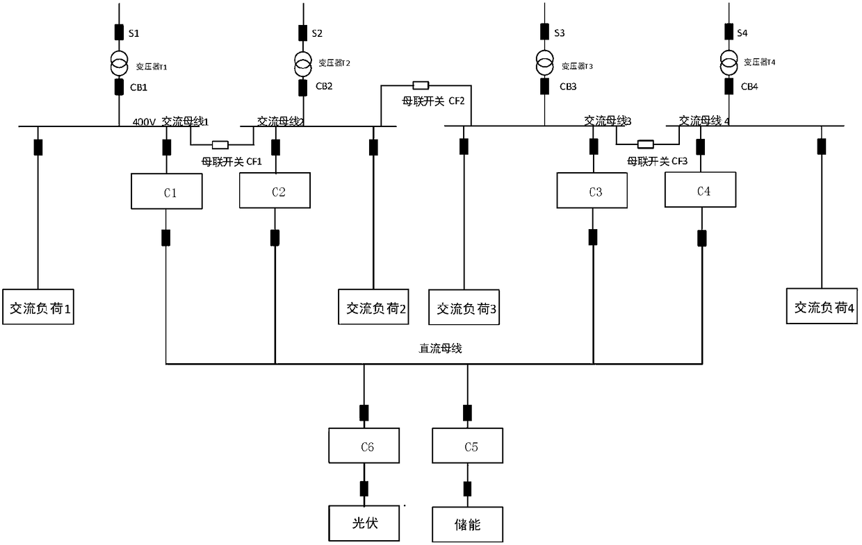
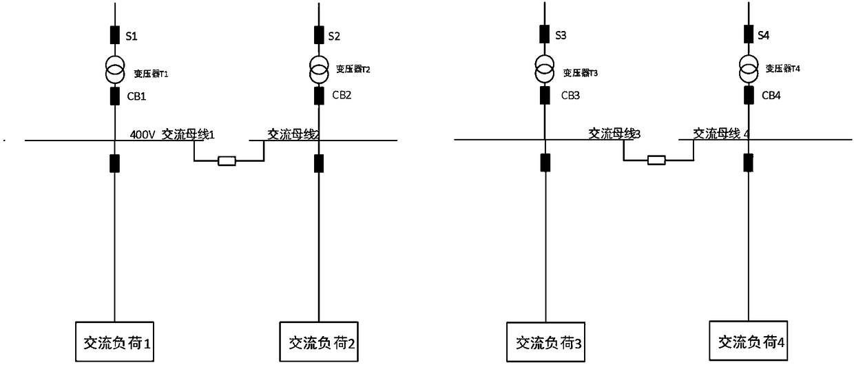
[0052] The four distribution transformers (distribution transformers) are defined as T1~T4, the high voltage side switches of the distribution transformers are respectively defined as S1~S4, and the low voltage side switches of the distribution transformers are defined as CB1~CB4; the 4 sections of 400V low voltage AC buses are connected through bus tie switches; Before the renovation design, the structure diagram of the power supply system of the power distribution room of Xinghuwan Community is as follows figure 2 shown.

[0053] When the load of...


PUM


Abstract

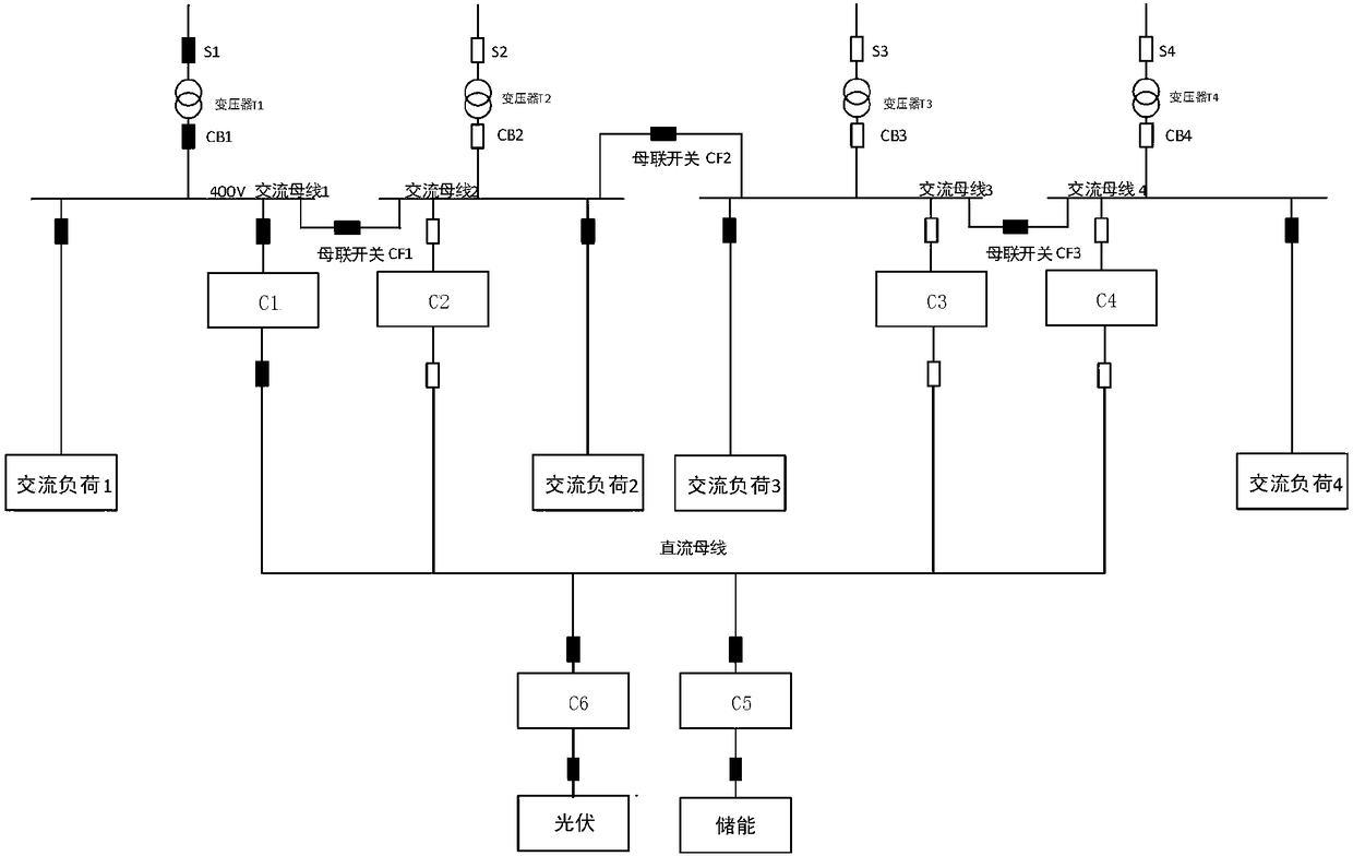
The invention provides a coordinated control method for a low-voltage flexible distribution network power supply system. The system comprises four distribution transformers T1-T4, four sections of 400V low-voltage AC (alternating current) buses and four flexible DC (direct current) converters, wherein the four sections of 400V low-voltage AC buses are connected through bus coupler switches; a DC bus is further connected to an energy storage system and a distributed photovoltaic system. The coordinated control method is used for performing coordinated control for different fault conditions of bus coupler switch fault, incoming line power loss, flexible direct current converter fault, energy storage converter fault and photovoltaic converter fault in different operation modes. According to the system, interconnection of multiple lines of the distribution network is realized by the flexible DC converters, power wheeling support between the lines is realized, and after a certain distribution line fails and breaks, the flexible DC converters perform islanded operation with load; meanwhile, interconnection is realized on the DC link with photovoltaic and energy storage systems, and an optical storage and flexible DC combined hybrid system is formed.

Description

technical field [0001] The invention belongs to the technical field of flexible power transmission, and in particular relates to a coordinated control method for a low-voltage flexible distribution network power supply system. Background technique [0002] Due to its unique technical advantages, flexible DC transmission is introduced into the urban power grid with intensive power consumption, and its rapid controllability is used to solve the problems of power supply difficulties, high costs and difficult power flow control in urban power supply. There are also broad application prospects in power distribution. First, the active power transmitted by flexible DC transmission can be quickly and flexibly controlled, and the power flow between different lines in the distribution network can be effectively and feasiblely allocated; secondly, flexible DC transmission can dynamically compensate the AC bus. The reactive power is conducive to the grid-connection of distributed power ...

Claims


Application Information

Patent Timeline
IPC IPC(8): H02J3/36H02J3/00H02J3/06H02J3/28H02J3/38H02J3/16
CPCH02J3/383H02J3/06H02J3/16H02J3/28H02J3/36H02J3/0073H02J3/388Y02E10/56Y02E40/30Y02E60/60Y02E70/30
Inventor 张伟胡凯刘洋陈颖滕松
Owner JIANGSU ELECTRIC POWER CO
Learn More