Flat wire continuous wave staggered winding and stator comprising same

A technology of wave winding and flat wire, which is applied in the field of flat wire continuous wave winding dislocation winding and stators containing flat wire continuous wave winding dislocation winding, can solve problems such as easy failure, high manufacturing cost, and complicated motor circuit design, and achieve Improve product quality, reduce noise, reduce the effect of the second harmonic

Pending Publication Date: 2018-09-14
CHANGYING XINZHI TECH CO LTD
View PDF0 Cites 16 Cited by
  • Summary
  • Abstract
  • Description
  • Claims
  • Application Information

AI Technical Summary

Problems solved by technology

[0005] However, the above-mentioned S-shaped waveform coil, such as figure 1 As shown, when winding, the pitches of the effective sides of the S-shaped wavy lines of each line in each phase line are equal, and the effective sides of the S-shaped wavy lines of each line in each phase line are placed in sequence In the stator slot body, for the above-mentioned motor stator, the number of slots distributed per pole and phase is equal to the number of controllers to be controlled. For

Method used


Image

  • Flat wire continuous wave staggered winding and stator comprising same
  • Flat wire continuous wave staggered winding and stator comprising same
  • Flat wire continuous wave staggered winding and stator comprising same

Examples


Embodiment 1

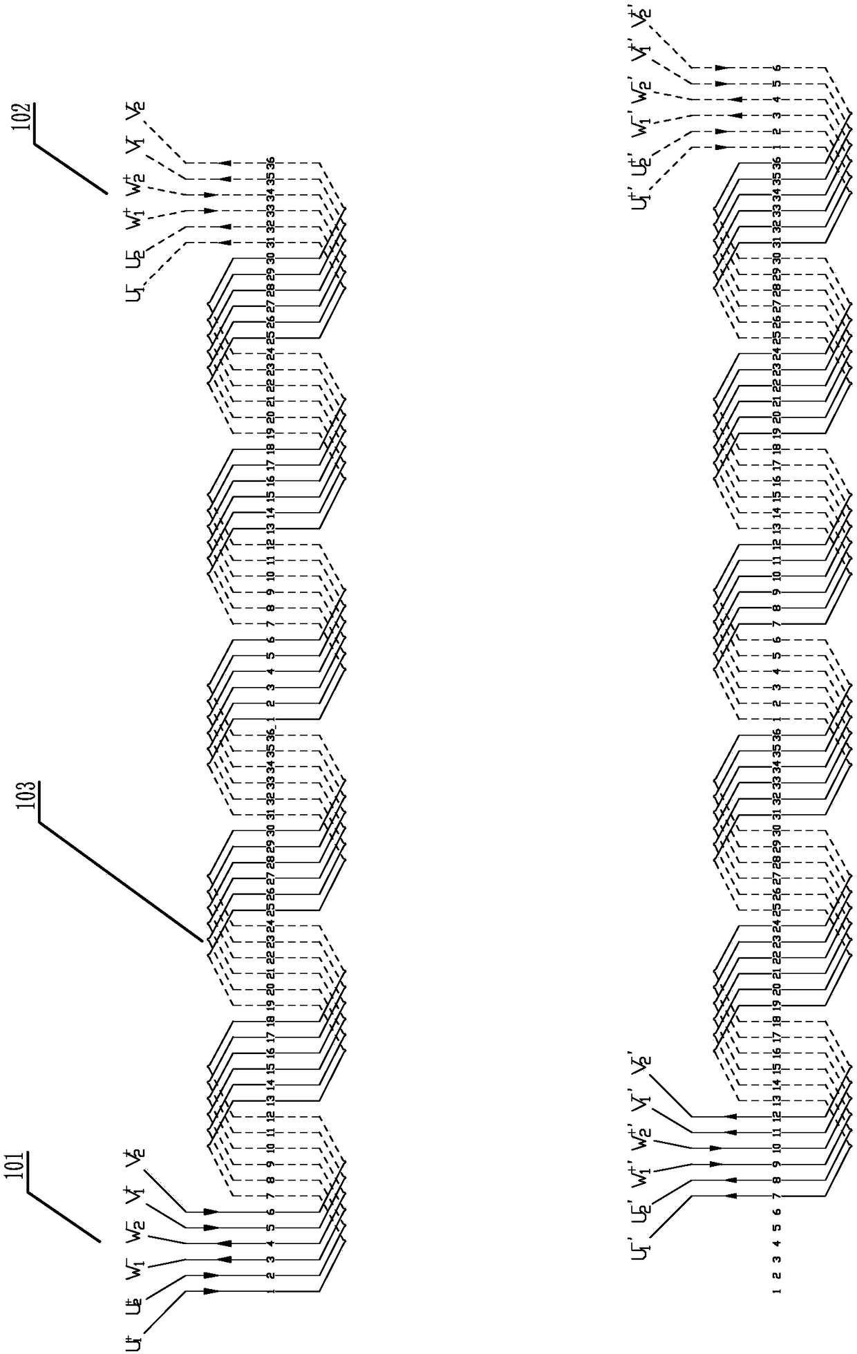
[0079] Example 1: Take a motor with two slots per pole and one phase as an example, such as Figure 4 , Figure 5 The dislocation winding of a continuous wave of a flat wire is shown, which consists of an incoming wire part 101, an outgoing wire part 102, and an S-shaped winding between the incoming wire part 101 and the outgoing wire part 102. The S-shaped wavy line 103 is composed of an S-shaped wavy line 103 including an effective side portion 301 for placing in the stator slot body 503, a straight line portion 302 located outside the two sides of the slot body 503, and an end portion 303 connecting adjacent straight line portions 302; In the S-shaped corrugated wire 103, a dislocation winding part 104 is provided, and the position of the dislocation winding part 104 is arranged in a dislocation arrangement between the conductors in each phase conductor, and the dislocation winding part 104 is arranged in the middle of the entire waveform wire Position, according to the nu...

Embodiment 2

[0086] Embodiment 2: Take a motor with two slots per pole and one phase as an example, such as Figure 9 The flat wire continuous wave wound dislocation winding shown has the same basic structure as that of Embodiment 1. In the S-shaped wave wire 103, a dislocation winding part 104 is provided, but for the dislocation winding part 104, according to each pole and each phase For the number of distributed slots q, one misplaced winding part 104 is provided in the co-directional wave winding formed by the three phases U, V, and W every other wave winding. Taking the 36-slot motor as an example, in the S-shaped waveform line 103, five co-directional wave windings with the ends 303 above the effective side portion 301 are included, namely, the first wave winding, the second wave winding, the third wave winding, and the first wave winding. For the four-wave winding and the fifth-wave winding, the first-wave winding, the third-wave winding, and the fifth-wave winding are respectively ...

Embodiment 3

[0088] Embodiment 3: Take a motor with 3 slots per pole and each phase as an example, such as Figure 10 , Figure 11 Shown is a flat wire continuous wave winding with a dislocation winding, and other structures are the same as in Embodiment 1. In the S-shaped corrugated wire 103, a dislocation winding part 104 is provided, and the wires in each phase wire of the dislocation winding part 104 are mutually The position between them is set as a misplaced arrangement. The misplaced winding part 104 is set in the middle of the entire waveform line. According to the number of slots q distributed in each pole and phase is 3, for the U, V, W three-phase winding composed of three-phase windings in the entire waveform The wave winding in the S-shaped waveform line 103 in the middle of the line, in the U-phase line, U 1 line pitch y 1 for: y 1 =q×m+(q-1)=3×3+(3-1)=11, U 2 line pitch y 2 for: y 2 = q× m-1= 3×3-1=8, U 3 line pitch y 3 for: y 3 = q× m-1= 3×3-1=8; in the V phase li...


PUM


Abstract

The invention discloses a flat wire continuous wave staggered winding and a stator comprising the same and belongs to the technical field of motor manufacture. The flat wire continuous wave staggeredwinding is composed of a wire inlet end lead part (101), a wire outlet end lead part (102) and an S-shaped S wave line (103). The S-shaped wave line (103) includes an active side part (301), a straight line part (302) and an end part (303). The S-shaped wave line (103) is provided with a staggered winding part (304) in which the leads of different phases are arranged in a staggered manner. According to the invention, single three-phase control can be realized for motors or generators with different slot number of each phase and each electrode. Therefore, a motor circuit can be simplified and manufacture cost can be reduced. Secondary harmonics of the motor can be reduced, motor noise can be reduced and product quality can be improved.

Description

technical field [0001] The invention relates to the technical field of motor manufacturing, in particular to an AC motor, including a motor and a generator, and in particular to a continuous-wave flat-wire wound dislocation winding and a stator containing a flat-wire continuous-wave wound dislocation winding. Background technique [0002] For rotating electrical machines, in order to enhance the performance of rotating electrical machines, it is necessary to increase the space factor of the stator in the slot and increase the slot fullness rate. Therefore, it is a feasible way to use flat wires with rectangular cross-sections as materials for forming stator windings. It is also a better method. [0003] On March 26, 1998, the Chinese invention patent with the application number 981078494 discloses an alternator for automobiles, the multi-phase stator winding includes a plurality of electrical conductors, and the plurality of electrical conductors constitute at least one pair...

Claims


Application Information

Patent Timeline
IPC IPC(8): H02K3/12H02K1/16H02K3/16
CPCH02K1/16H02K3/12H02K3/16H02K2213/03H02K3/28
Inventor 王健欢
Owner CHANGYING XINZHI TECH CO LTD
Why Eureka
Try Eureka