
Welding method loading cold source and displacement-controlled load in welding

A technology of displacement control and welding method, which is applied in the direction of welding equipment, welding equipment, auxiliary welding equipment, etc., and can solve the problems of unreachable effect, unsatisfactory local heat treatment effect of large structural parts, reheat cracks, etc.

Active Publication Date: 2018-09-18
LIAONING UNIVERSITY OF PETROLEUM AND CHEMICAL TECHNOLOGY
View PDF5 Cites 3 Cited by
  • Summary
  • Abstract
  • Description
  • Claims
  • Application Information

AI Technical Summary

Problems solved by technology

Among the above methods, the effect of post-weld heat treatment is the best, but it is only suitable for the overall heat treatment of small structural parts, and the local heat treatment effect of large structural parts is still unsatisfactory.
Moreover, post-weld heat treatment consumes a lot of energy. If the heat treatment temperature and time are not properly controlled, it will lead to embrittlement and even reheat cracks.
If the prediction is inaccurate in the pre-welding measures, the effect will not be achieved, and if the post-welding measures are not timely, it will not help

Method used


Image

  • Welding method loading cold source and displacement-controlled load in welding
  • Welding method loading cold source and displacement-controlled load in welding

Examples


Embodiment Construction

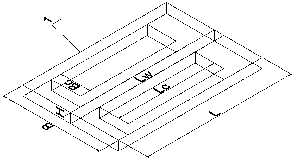
[0017] Such as figure 1 , figure 2 The length L=0.2m, the width B=0.15m, the thickness H=0.004m, the length L of the welding seam shown in the weldment 1 w =0.2m, the length of the range of cold source L c =0.2m, width B c =0.04m, welding speed v w =0.003m / s, welding current I=180A, welding voltage U=27V, the maximum allowable temperature drop of the steel plate within the scope of the cold source is ΔT c =20℃, cold source power is P _ =1000w. Steel specific heat capacity c=460J / (kg℃), density ρ=7850kg / m 3 , Expansion coefficient α=1.2E-5 / ℃, steel plate surface convective heat transfer coefficient h=10W / (m 2 ℃).

[0018] The inventive method comprises the following concrete steps:

[0019] 1. Calculation of relevant parameters: the displacement growth rate of the tensile load perpendicular to the weld is The displacement growth rate of the tensile load parallel to the weld is The unloading time of mechanical tensile displacement load is about The displacement u...


PUM

PropertyMeasurementUnit
lengthaaaaaaaaaa
widthaaaaaaaaaa
thicknessaaaaaaaaaa

Abstract

The invention discloses a welding method loading a cold source and displacement-controlled load in welding. The method comprises the following steps of: applying the cold source which has certain power to other positions of a welding part before a welding heat source is applied and in the welding heat source applying process; and if the power of the cold source is insufficient, simultaneously applying displacement-controlled mechanical tensile load in the length direction of a welding seam and in the direction perpendicular to the welding seam. According to the method, the cold source having the certain power acts on other positions of the welding part when the welding heat source is in action; if the total deformation generated by cooling shrinkage in the region is equal to that generatedby free thermal expansion of a heated position, the expansion of the heated position is not hindered, the stress is zero, and plastic deformation is prevented. If the power of the cold source is limited, the total deformation generated by cooling shrinkage is smaller than that generated by the free thermal expansion of the heated position, then the four sides of the welding part can be simultaneously applied with the mechanical tensile load, certain tensile elastic deformation is generated in the overall welding part or in a local part of the welding part so as to compensate or counteract a part of the free thermal expansion deformation of the heated position. In practice, low-stress and plastic-deformation-free welding can be realized, the pressure stress inside the welding part is reduced, and deformation, caused by instability, of a thin plate is prevented.

Description

1. Technical field [0001] The invention belongs to the technical field of welding, and in particular relates to a welding method for loading a cold source along with welding and controlling load with displacement. 2. Background technology [0002] The welded structure will generate high stress during welding, and the welded structure is prone to large deformation and even cracks. Welding stress poses a great threat to the safety of structures. According to the sequence relative to the welding process, the existing measures to control the stress of welded structures can be divided into three modes: before welding, during welding and after welding. Pre-welding measures include preheating, pre-stretching along the length of the weld, reverse deformation, etc.; welding measures include welding rolling, point-by-point extrusion, welding hammering, temperature difference stretching, LSND, and welding rotary extrusion etc.; post-weld measures include post-weld heat treatment, ove...

Claims


Application Information

Patent Timeline
Patent Type & Authority Applications(China)
IPC IPC(8): B23K31/02B23K37/00
CPCB23K31/02B23K37/003
Inventor 管建军钟宏远赵艳宋天民陈怀宁刘峰蒋应田
Owner LIAONING UNIVERSITY OF PETROLEUM AND CHEMICAL TECHNOLOGY
Learn More