Broadband chaos radar device based on optical simulation related receiver

A technology for optical simulation and radar devices, applied in measuring devices, radio wave reflection/re-radiation, re-radiation utilization, etc., can solve the problems of slow signal processing speed, nonlinear distortion of radar signals, and chaotic radars that cannot fully utilize transmitter efficiency And other issues

Active Publication Date: 2018-09-18
TAIYUAN UNIV OF TECH
View PDF5 Cites 2 Cited by
  • Summary
  • Abstract
  • Description
  • Claims
  • Application Information

AI Technical Summary

Problems solved by technology

At present, the biggest disadvantage of the digital correlation receiver used in broadband chaotic radar is that the signal processing speed is slow, and it takes a long time to calculate the distance of the target object, especially when measuring the moving object, it cannot reflect its real-time motion state and position
[0006] In addition, the signal transmitters currently used for broadband chaotic radar signals generally transmit the chaotic signal generated by the signal source directly or after simple modulation with a sinusoidal carrier; Average Ratio, PAPR) is relatively high, because the dynamic range of the power amplifier in the radar is limited, therefore, a high PAPR will not only cause the chaotic radar to not fully utilize the efficiency of the transmitter, but also make the radar signal easily enter the power The nonlinear region of the amplifier causes nonlinear distortion of the radar signal, causing obvious spectrum spread interference and in-band signal distortion, resulting in a serious decline in the performance of the entire radar system

Method used


Image

  • Broadband chaos radar device based on optical simulation related receiver
  • Broadband chaos radar device based on optical simulation related receiver
  • Broadband chaos radar device based on optical simulation related receiver

Examples


Embodiment Construction

[0021] The specific implementation of the present invention will be described in detail below in conjunction with the accompanying drawings.

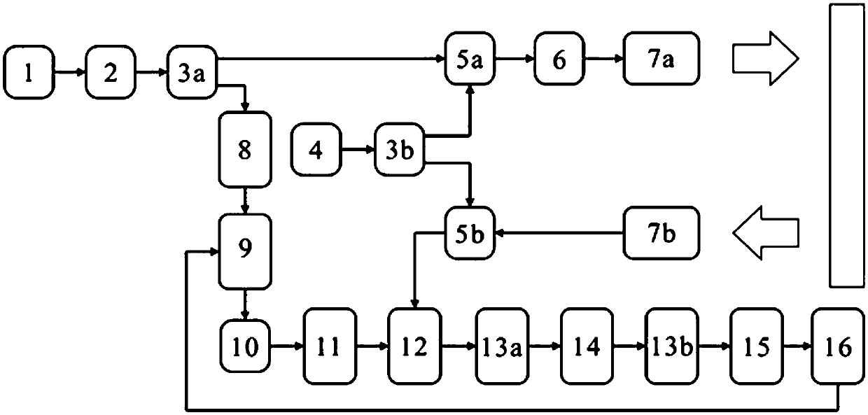
[0022] Such as figure 1 As shown, a broadband chaotic radar system based on an optical analog correlation receiver includes a signal transmitter, a signal receiver and a broadband antenna.

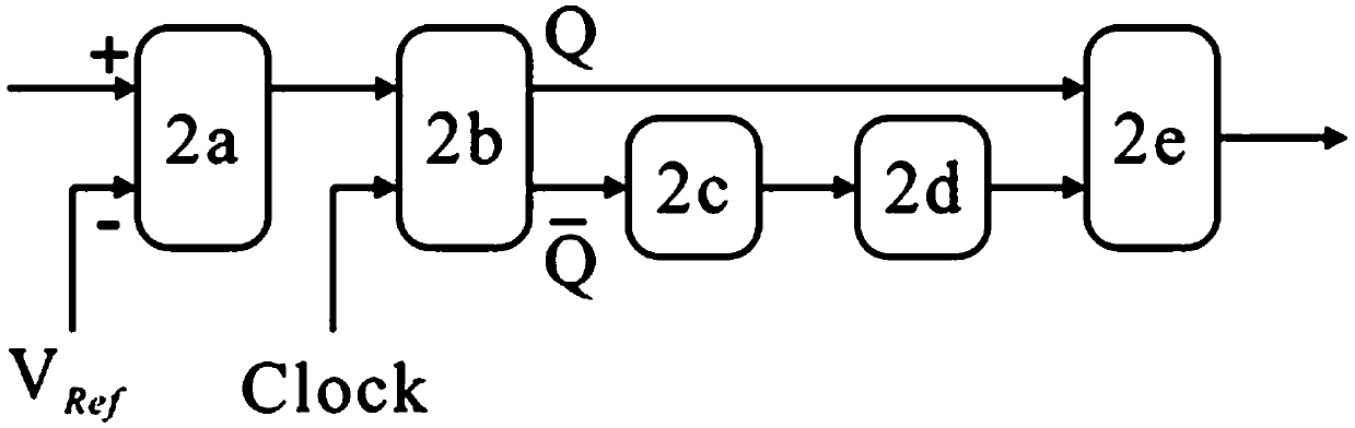
[0023] Described signal transmitter produces chaotic signal (-10dB bandwidth is greater than 500MHz) by broadband chaotic signal source 1, and chaotic signal input peak-to-average power ratio adjuster 2 carries out peak-to-average power ratio adjustment, and the output signal of peak-to-average power ratio adjuster 2 is passed through The first broadband power splitter 3a is divided into two paths: one path is used as the reference signal S after being delayed by the first electrical delay line 8 and attenuated by the programmable attenuator 9 1 (t); the other way is used as a detection signal, mixed with a high-frequency sinusoidal signal generat...


PUM


Abstract

The invention discloses a broadband chaos radar device based on optical simulation related receiver. The device is composed of a signal transmitter, a signal receiver and a broadband antenna. A broadband chaos signal source generates a chaos signal; and through a peak average ratio adjustor, the peak average power ratio of an output signal is kept to 2. Afterwards the signal is divided into two paths. One path of divided signal is transmitted by an antenna, and the other path is used as a reference signal. After the reference signal is delayed through a delay line, a frequency-converted echo signal is received at an acousto-optic correlator and a receiving antenna. An acousto-optic modulator realizes an acousto-optic interaction. Finally through diaphragm filtering and lens imaging, time integration is realized at a CCD. Finally a data processing and displaying module displays a result. The broadband chaos radar device is characterized in that an optical method is used for calculatinga cross correlation result of two simulation signals, thereby replacing a traditional digital calculation mode; and the broadband chaos radar device has advantages of high calculation speed, simple structure, etc.

Description

technical field [0001] The invention relates to the field of broadband radar design, in particular to a broadband chaotic radar device based on an optical analog correlation receiver, which can be applied to the fields of remote sensing, investigation, geophysical exploration and the like. Background technique [0002] Ultra-wideband (UWB) radar is a new system radar, because of its wide signal bandwidth (fractional bandwidth greater than 0.25), it has strong anti-stealth ability, small detection blind zone, high distance resolution, and anti-interference It is widely used in both military and civilian fields because of its strong anti-multipath ability. According to the different radar transmission waveforms, common UWB radars can be divided into shock pulse radar, linear frequency modulation continuous wave radar, step frequency modulation continuous wave radar and random noise radar and other systems. [0003] Wideband chaotic radar is a new type of ultra-wideband radar ...

Claims


Application Information

Patent Timeline
Patent Type & Authority Applications(China)
IPC IPC(8): G01S13/58G01S13/06
CPCG01S13/06G01S13/58
Inventor 张建国徐航孙浩彦刘丽李静霞
Owner TAIYUAN UNIV OF TECH
Why Eureka
Try Eureka