
Lead slag salvaging device

A lead slag and chute technology, which is applied in the field of mining and metallurgy equipment, can solve problems such as poor working conditions, impact on the quality of lead ingots, and worker hazards, and achieve the effects of meeting the requirements of slag removal, stable slag removal process, and high production efficiency

Pending Publication Date: 2018-09-28
KUNMING UNIV OF SCI & TECH
View PDF0 Cites 5 Cited by
  • Summary
  • Abstract
  • Description
  • Claims
  • Application Information

AI Technical Summary

Problems solved by technology

[0002] In the electrolytic lead casting process, since the lead liquid is injected into the mold, the temperature of the lead liquid is very high, other metal impurities contained in the lead liquid oxidize with the oxygen in the air to generate some oxide particles, which are suspended in the lead liquid Among them, this has a great impact on the quality of lead ingots, so removing these lead slags has become an indispensable link in the electrolytic lead casting process. The slag removal process is an important process in the production of electrolytic lead casting. It is also one of the worst working conditions. At present, the traditional manual method of removing scum by mold is still used in the domestic and foreign lead casting industry. Since lead is a heavy metal, it is very harmful to the human body. Lead vapor is harmful to workers. Workers in slag removal work have been in close contact with liquid lead for a long time, and metallic lead enters the human body through the respiratory tract and skin, causing lead poisoning occupational diseases.

Method used


Image

  • Lead slag salvaging device
  • Lead slag salvaging device
  • Lead slag salvaging device

Examples


Embodiment 1

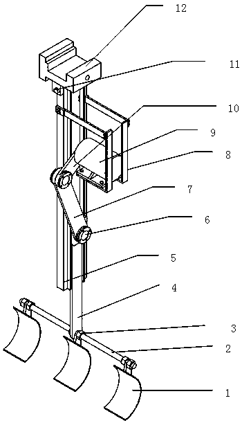
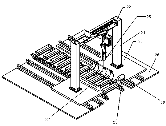
[0022] Embodiment 1: as Figure 1-4 As shown, a lead slag removal device includes a chute mechanism 22, a slag removal arm 25, a synchronous motor 19, a moving slide 20, a support column 21, a claw hook 24, a base 26 and a slag storage box 27;

[0023] Wherein the chute mechanism 22 is installed on the mobile slide plate 20 through the support column 21, the mobile slide plate 20 is installed on the base 26 with guide rail, the slag removal arm 25 is connected with the chute mechanism 22, and is installed on the mobile slide plate 20 to synchronize the movement of the motor 19 The claw hook 24 is driven to catch the moving production line, and the movable slide plate 20 moves together with the production line. The movement of the drive motor II 15 in the chute mechanism 22 drives the slag removal arm 25 to move along the slag river on the roller 23, and the drive motor Ⅰ9 in the slag removal arm 25 The motion drives the slag removal arm 25 to move up and down, and the slag rem...


PUM


Abstract

The invention discloses a lead slag salvaging device. The lead slag salvaging device comprises a slide slot mechanism, a slag salvaging arm, a synchronous motor, a movable slide plate, a supporting post, a grabbing hook, a base and a slag storage box, wherein the slide slot mechanism is mounted on the movable slide plate through the supporting post; the movable slide plate is mounted on a base with a guide rail; the slag salvaging arm is connected with the slide slot mechanism; the synchronous motor mounted on the movable slide plate moves to drive the grabbing hook to hook a moving productionline, so that the movable slide plate moves along with the production line; a drive motor II in the slide slot mechanism moves to drive the slag salvaging arm to move along a slag river on a roller;a drive motor I in the slag salvaging arm moves to drive the slag salvaging arm to move up and down; the slag salvaging arm moves along the slag river on the roller; and the slag salvaging arm moves downwards and extends into the slag river, so that lead slag in the slag river is conveyed into the slag storage box. The lead slag salvaging device realizes mechanical production, is high in production efficiency, improves a high-temperature toxic manual slag salvaging condition, relieves labor intensity of manual slag salvaging, increases a production rate of molten lead cast ingots, and improvesproduct quality.

Description

technical field [0001] The invention relates to a lead slag removing device, which belongs to the technical field of mining and metallurgy equipment. Background technique [0002] In the electrolytic lead casting process, since the lead liquid is injected into the mold, the temperature of the lead liquid is very high, other metal impurities contained in the lead liquid oxidize with the oxygen in the air to generate some oxide particles, which are suspended in the lead liquid Among them, this has a great impact on the quality of lead ingots, so removing these lead slags has become an indispensable link in the electrolytic lead casting process. The slag removal process is an important process in the production of electrolytic lead casting. It is also one of the worst working conditions. At present, the traditional manual method of removing scum by mold is still used in the domestic and foreign lead casting industry. Since lead is a heavy metal, it is very harmful to the human ...

Claims


Application Information

Patent Timeline
Patent Type & Authority Applications(China)
IPC IPC(8): B22D43/00
CPCB22D43/00
Inventor 邓创姚廷强王学军王立华
Owner KUNMING UNIV OF SCI & TECH
Learn More