CO2 air conditioning heat pump system

A heat pump system and air-conditioning technology, which is applied in the field of air-conditioning heat pumps, can solve problems such as increasing energy consumption, shortening battery life, and reducing battery performance, so as to achieve the effects of improving work performance, improving use efficiency, and improving battery life

Active Publication Date: 2018-09-28
XI AN JIAOTONG UNIV
View PDF8 Cites 6 Cited by
  • Summary
  • Abstract
  • Description
  • Claims
  • Application Information

AI Technical Summary

Problems solved by technology

On the one hand, such an auxiliary heating device complicates the system and increases the equipment cost; on the other hand, it increases the energy consumption of the system during operation and reduces the heating efficiency of the system, but its work performance and efficiency still need to be further improved
In addition, because electric vehicles rely on battery life and drive in an extremely unstable environment for a long time, the battery pack of electric vehicles will work in a harsh thermal environment for a long time, which will shorten the service life of the battery and reduce the performance of the battery
Moreover, the long-term uneven distribution of the temperature field in the battery box will cause the performance of each battery module and monomer to be unbalanced. Therefore, the thermal monitoring and management of the battery pack is of great significance to the safety of the entire vehicle.
[0004] The traditional automotive air-conditioning system does not have a detailed and clear temperature control system for the temperature field in the car. It is impossible to efficiently and accurately control the temperature inside the car while optimizing the system performance and saving energy.

Method used


Image

  • CO2 air conditioning heat pump system
  • CO2 air conditioning heat pump system
  • CO2 air conditioning heat pump system

Examples


Embodiment Construction

[0035] The present invention will be described in further detail below in conjunction with the accompanying drawings.

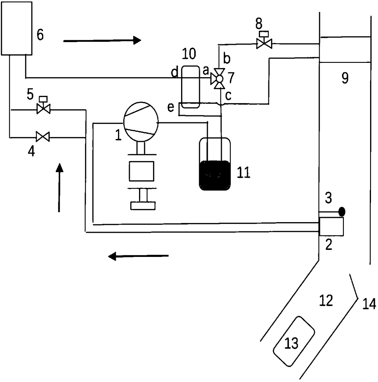
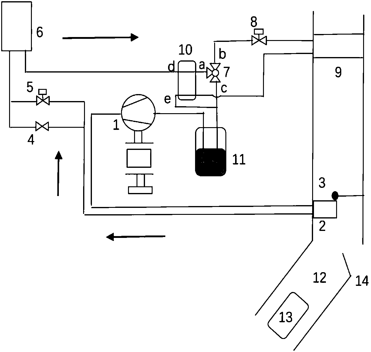
[0036] see figure 1 , electric vehicle air conditioning thermal management technology, including: compressor 1, indoor gas cooler 2, damper 3, bypass valve 4, expansion valve 5, outdoor heat exchanger 6, three-way valve 7, expansion valve 8, indoor Heat exchanger 9 , regenerator 10 , accumulator 11 , air duct 12 , battery temperature controller 13 and air valve 14 .

[0037] The three-way valve 7 includes three ports of a port, b port and c port;

[0038] The outlet of the compressor 1 is connected to the inlet of the indoor gas cooler 2, the outlet of the indoor gas cooler 2 is connected to the inlet of the bypass valve 4 and the expansion valve 5, and the inlet of the outdoor heat exchanger 6 is connected to the inlet of the bypass valve 4 and the expansion valve 5 Outlet, the d-end inlet of the regenerator 10 is connected to the outlet of the outdoor hea...


PUM


Abstract

The invention discloses a CO2 air conditioning heat pump system. An outlet of a compressor is connected with an inlet of an indoor gas cooler; an outlet of the indoor gas cooler is connected with inlets of a bypass valve and an expansion valve; an inlet of an outdoor heat exchanger is connected with outlets of the bypass valve and the expansion valve; a d-end inlet of a heat regenerator is connected with an outlet of the outdoor heat exchanger; a d-end outlet of the heat regenerator is connected with a port a of a three-way valve; a port b of the three-way valve is connected with one end of the expansion valve; a port c of the three-way valve is connected with an e-end outlet of the heat regenerator and an inlet of an energy accumulator; an inlet of an indoor heat exchanger is connected with the other end of the expansion valve; an outlet of the indoor heat exchanger is connected with an e-end inlet of the heat regenerator; the e-end outlet of the heat regenerator is connected with aninlet of the energy accumulator; and an outlet of the energy accumulator is connected with an inlet of the compressor. According to the CO2 air conditioning heat pump system, by reasonably arranging asystem process, the expansion valve and various electromagnetic valves are opened and closed by using a control unit; and therefore, conversion among three modes of a refrigeration mode, a heating mode and a dehumidification mode, and the functions of the unit are comprehensive.

Description

technical field [0001] The invention belongs to the technical field of air-conditioning heat pumps, in particular to a CO 2 Air conditioning heat pump system. Background technique [0002] Electric vehicles overcome the dependence on fossil fuels of fuel vehicles, with diversified energy utilization, quietness and environmental protection, representing the trend of future automobile development. In the high-temperature environment in summer, the temperature inside the electric vehicle compartment is too high, so the car air conditioner is needed to cool down, so that the air temperature in the compartment drops to the comfort level; in terms of heating in winter, since the pure electric vehicle has no engine waste heat to use, Therefore, at present, pure electric vehicles basically use PTC electric heating for heating in winter. However, the battery storage capacity of pure electric vehicles is limited, and the use of electric heating for heating will inevitably affect the ...

Claims


Application Information

Patent Timeline
Patent Type & Authority Applications(China)
IPC IPC(8): B60H1/00
CPCY02B30/52B60H1/00007
Inventor 曹锋王静殷翔殷叔靖漆鹏程
Owner XI AN JIAOTONG UNIV
Why Eureka
Try Eureka