V-profile opened current transformer and production process thereof

A technology of current transformers and transformers, applied in the direction of inductors, transformers/inductor shells, transformers/inductor cores, etc., can solve the expectation of reducing the magnetic permeability of transformers, poor magnetic permeability and unstable performance and other problems to achieve the effect of increasing the effective contact area, simplifying the production process and improving production efficiency

Pending Publication Date: 2018-09-28
华建电气有限公司
View PDF0 Cites 3 Cited by
  • Summary
  • Abstract
  • Description
  • Claims
  • Application Information

AI Technical Summary

Problems solved by technology

The biggest difficulty encountered in the practical application of the open current transformer is that the closed-loop iron core itself is cut into two semi-circular rings, which are closed again during use, and there will be a certain air gap between the closed contact surfaces. , resulting in a large number of magnetic field lines not closing on the original magnetic circuit of the iron core, resulting in magnetic flux leakage, which greatly reduces the expectation of the transformer for the magnetic permeability that the iron core should have.
The existing open-type current transformer has the defects of unstable performance, large magnetic flux leakage, and poor magnetic permeability

Method used


Image

  • V-profile opened current transformer and production process thereof
  • V-profile opened current transformer and production process thereof
  • V-profile opened current transformer and production process thereof

Examples


Embodiment Construction

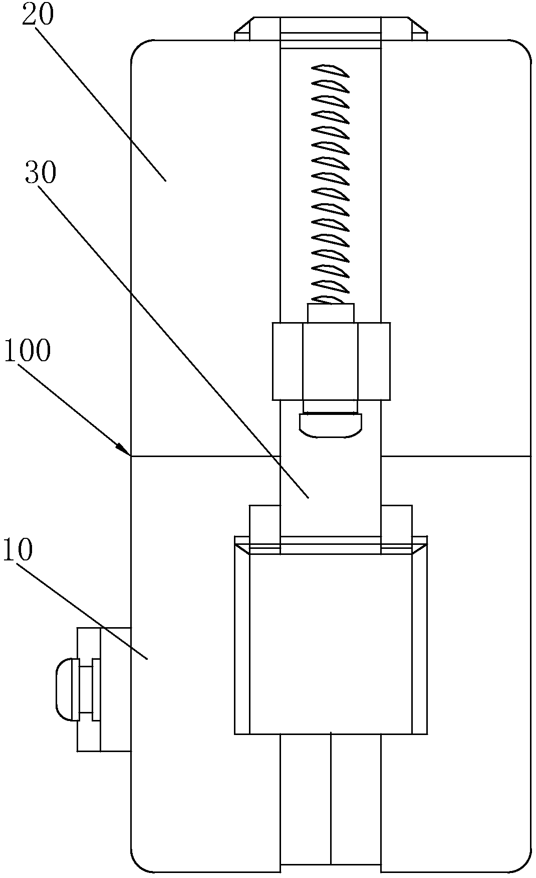
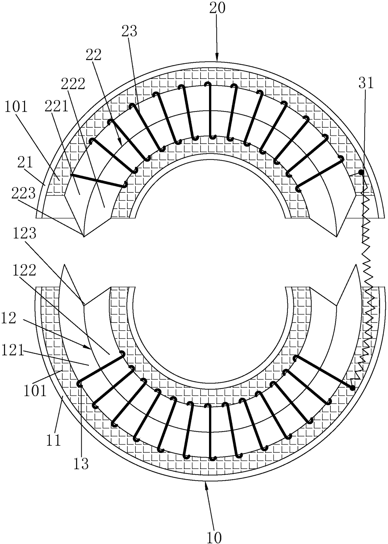
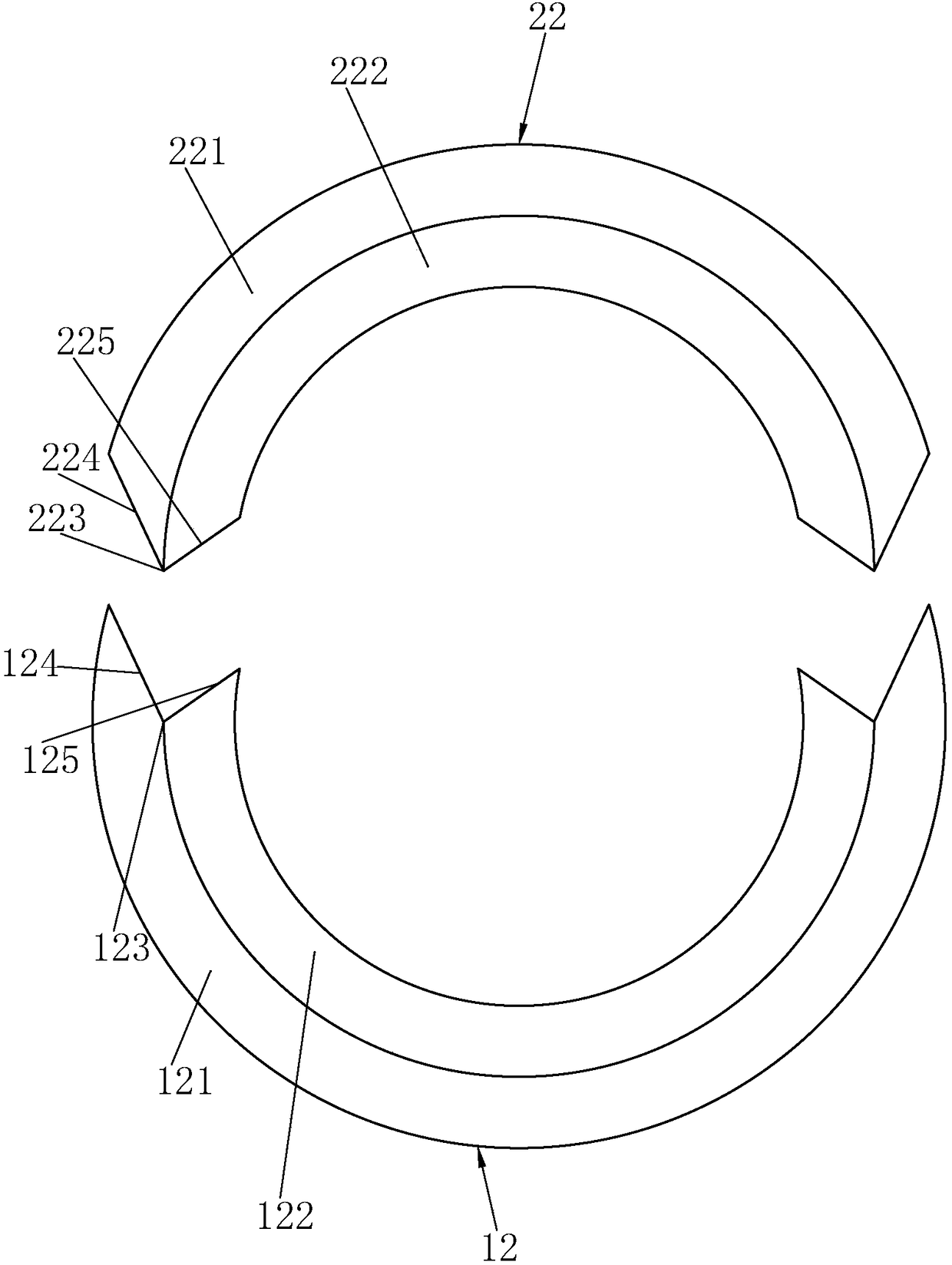
[0020] like Figure 1~4 As shown, the embodiment of the present invention is a V-shaped open-type current transformer, including a first transformer body 10, a second transformer body 20 combined with the first transformer body 10, and a second transformer body connected to the second transformer body 10. A metal locking band 30 between a transformer body 10 and a second transformer body 20, the first transformer body 10 includes a first cast plastic shell 11, and is arranged in the first cast plastic shell 11 The first semi-circular core 12, the first secondary coil 13 wound on the first semi-circular core 12, the first pouring plastic shell 11 and the first semi-circular core 12, the first Epoxy resin 101 is poured between the secondary coils 13, and the second transformer body 20 includes a second cast plastic shell 21, a second semicircular iron core 22 arranged in the second cast plastic shell 21, The second secondary coil 23 wound on the second semi-circular iron core 2...


PUM


Abstract

The invention relates to a V-profile opened current transformer. The V-profile opened current transformer comprises a first mutual inductor body, a second mutual inductor body and a metal locking tape, wherein the first mutual inductor body comprises a first pouring plastic shell, a first half-circular iron core and a first secondary coil, the second mutual inductor body comprises a second pouringplastic shell, a second half-circular iron core and a second secondary coil, the first half-circular iron core is formed by splicing a first large half-circular iron core and a first small half-circular iron core, V-shaped contact concave surfaces are respectively formed at two ends of the first half-circular iron core, the second half-circular iron core is formed by splicing a second large half-circular iron core and a second small half-circular iron core, V-shaped contact convex surfaces are respectively formed at two ends of the second half-circular iron core, and the contact convex surfaces and the contact concave surfaces are spliced to form a circular mutual inductor body. The V-profile opened current transformer has the advantages of simple structure, stable and reliable performance, small magnetic leakage and high magnetic conductivity.

Description

technical field [0001] The invention relates to an open current transformer, in particular to a V-shaped surface open current transformer and a production process thereof. Background technique [0002] At present, with the rapid development of my country's economy, the demand for electric energy in the whole society is increasing, and the requirements are getting higher and higher, forcing the continuous improvement and updating of power system technology, and putting forward higher requirements for power equipment. Turn on the current transformer as one of the important measurement and protection electrical components in the power system, some of which have been put into operation, and have achieved certain economic and social benefits. The biggest difficulty encountered in the practical application of the open current transformer is that the closed-loop iron core itself is cut into two semi-circular rings, which are closed again during use, and there will be a certain air ...

Claims


Application Information

Patent Timeline
IPC IPC(8): H01F38/30H01F27/24H01F27/34H01F27/02H01F27/28H01F41/00H01F41/02H01F41/06
CPCH01F27/022H01F27/24H01F27/28H01F27/346H01F38/30H01F41/00H01F41/005H01F41/0206H01F41/06H01F2038/305
Inventor 戴建尧
Owner 华建电气有限公司
Why Eureka
Try Eureka