Control method of three-phase pwm rectifier under the condition of rapid and large fluctuation of grid voltage

A technology of grid voltage and control method, applied in electrical components, output power conversion devices, conversion of AC power input to DC power output, etc., to achieve great application prospects and avoid the effect of oscillation problems

Active Publication Date: 2020-08-25
西安翌飞核能装备股份有限公司
View PDF5 Cites 0 Cited by
  • Summary
  • Abstract
  • Description
  • Claims
  • Application Information

AI Technical Summary

Problems solved by technology

[0004] The purpose of the present invention is to solve the problem of stable operation of the PWM rectifier under the condition of rapid and large fluctuations in grid voltage, and propose a new control method for the three-phase PWM rectifier
[0006] Compared with the prior art, the present invention adopts grid voltage feed-forward and bus voltage fluctuation feed-forward, and combines the two methods to solve the problem of stable operation of PWM rectifiers under fast and large fluctuation conditions

Method used


Image

  • Control method of three-phase pwm rectifier under the condition of rapid and large fluctuation of grid voltage
  • Control method of three-phase pwm rectifier under the condition of rapid and large fluctuation of grid voltage
  • Control method of three-phase pwm rectifier under the condition of rapid and large fluctuation of grid voltage

Examples


Embodiment Construction

[0021] Below in conjunction with specific embodiment and accompanying drawing, the present invention is described in further detail:

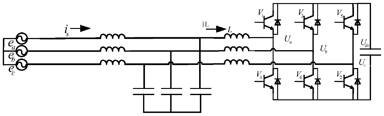
[0022] Such as figure 1 The PWM rectifier topology is shown: the topology uses a voltage-type three-phase converter, the power device uses IGBT, the inverter bridge is connected to the grid through LCL filtering, and the DC side uses a large-capacity electrolytic capacitor.

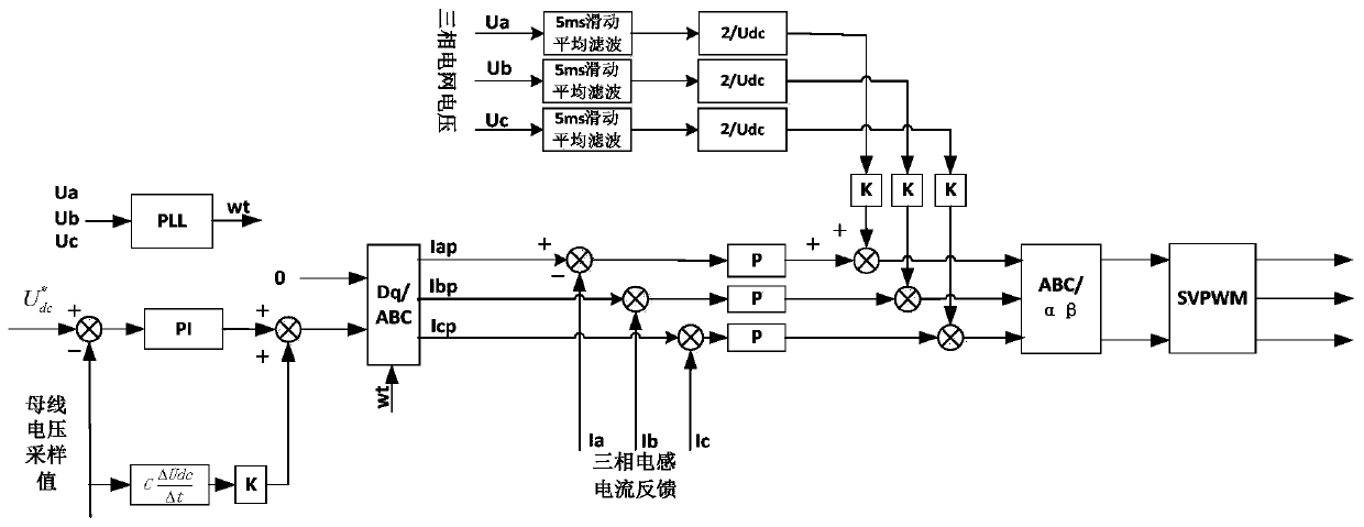
[0023] The control method implementation steps of the three-phase PWM rectifier of the present invention are as follows: figure 2 Shown:

[0024] a. Sampling the voltage of the three-phase grid, and using the soft phase-locking algorithm based on the instantaneous reactive power theory to lock the phase angle of the grid to obtain the grid angle θ.

[0025] b. Sampling the difference between the voltage value of the DC bus and the given voltage 800V to obtain the error signal, and use the PI regulator to control and adjust to obtain the signal Udc_k.

[0026] PI regula...


PUM


Abstract

The invention discloses a method for controlling a three-phase PWM rectifier under the rapid and sharp fluctuation condition of the voltages of a power grid. According to the method of the invention,a power grid voltage feedforward and bus voltage fluctuation feedforward combined method is adopted to realize the stable operation of the PWM rectifier under rapid fast and sharp fluctuation condition. The method includes the following steps that: 1) three-phase power grid voltages are sampled, a moving average filter of which the cutoff frequency is selected from frequencies at the vicinity of asystem bandwidth frequency is adopted to perform filtering on the voltages, and the filtered voltages are fed forward to current loop output; and 2) the voltages of a direct-current bus-bar are sampled, the fluctuation change amount of the current of the direct-current bus-bar is solved on the basis of the change amount of the voltages, and the fluctuation change amount of the current of the direct-current bus-bar is fed forward to direct-current bus-bar voltage loop output. The two modes are combined together, and therefore, an oscillation problem caused by high-frequency feedforward can beavoided, and the problem of feedforward effect alleviation caused by delay brought about by filtering can be solved.

Description

technical field [0001] The invention belongs to the field of power electronic control and relates to a control method of a PWM rectifier. Background technique [0002] In the field of distribution network, because the general system capacity is not large, and there are many sites with impact loads, because the impact loads work repeatedly, the voltage of the grid fluctuates relatively quickly and violently, such as the electric arc furnace at the moment of steel rolling in a steel mill. The power is very large, and multiple equipments randomly roll steel, resulting in very frequent and severe fluctuations in the grid voltage. Another example is the oil exploration site, the random operation of multiple kowtow machines leads to violent fluctuations in the grid voltage. Similar are aluminum factories, automobile manufacturing, etc. For such on-site power supply with PWM rectifier, or PWM rectifier equipment such as APF and SVG, it must have very good adaptability to the rapi...

Claims


Application Information

Patent Timeline
Patent Type & Authority Patents(China)
IPC IPC(8): H02M7/219
CPCH02M7/2173H02M7/219
Inventor 苏伟锋
Owner 西安翌飞核能装备股份有限公司
Why Eureka
Try Eureka