
Portable remote laser obstacle removal device for foreign matter on power transmission line

A power transmission line, portable technology, applied in the direction of overhead line/cable equipment, etc., can solve the problems of high energy divergence of the laser light path, low efficiency without conversion, large volume of the laser tube, etc., to achieve good beam quality, no preparation time, energy high effect

Inactive Publication Date: 2018-10-02
广东翼景信息科技有限公司
View PDF0 Cites 7 Cited by
  • Summary
  • Abstract
  • Description
  • Claims
  • Application Information

AI Technical Summary

Problems solved by technology

[0002] In the existing technology, the foreign matter removal methods of transmission lines mainly include manual climbing and removal, unmanned aerial vehicle fire removal, insulated arm truck lift-off and picking, etc. However, due to technical limitations, there is a safety risk when the removal instrument is too close to the live equipment , or the work takes a long time, the work intensity is high, and the labor risk is high.
The current laser power grid has invested a small amount of applicable remote laser obstacle removal system. Using the traditional carbon dioxide laser radiation principle, the laser tube is large in structure, and the conversion efficiency is low, and the weight of the whole machine is also mentioned. 40-50KG, the laser light path energy The divergence is high, and the operating distance is only 120m. In the actual application process, there are criticisms such as low efficiency, high energy consumption, complicated operation, and inconvenient movement.

Method used

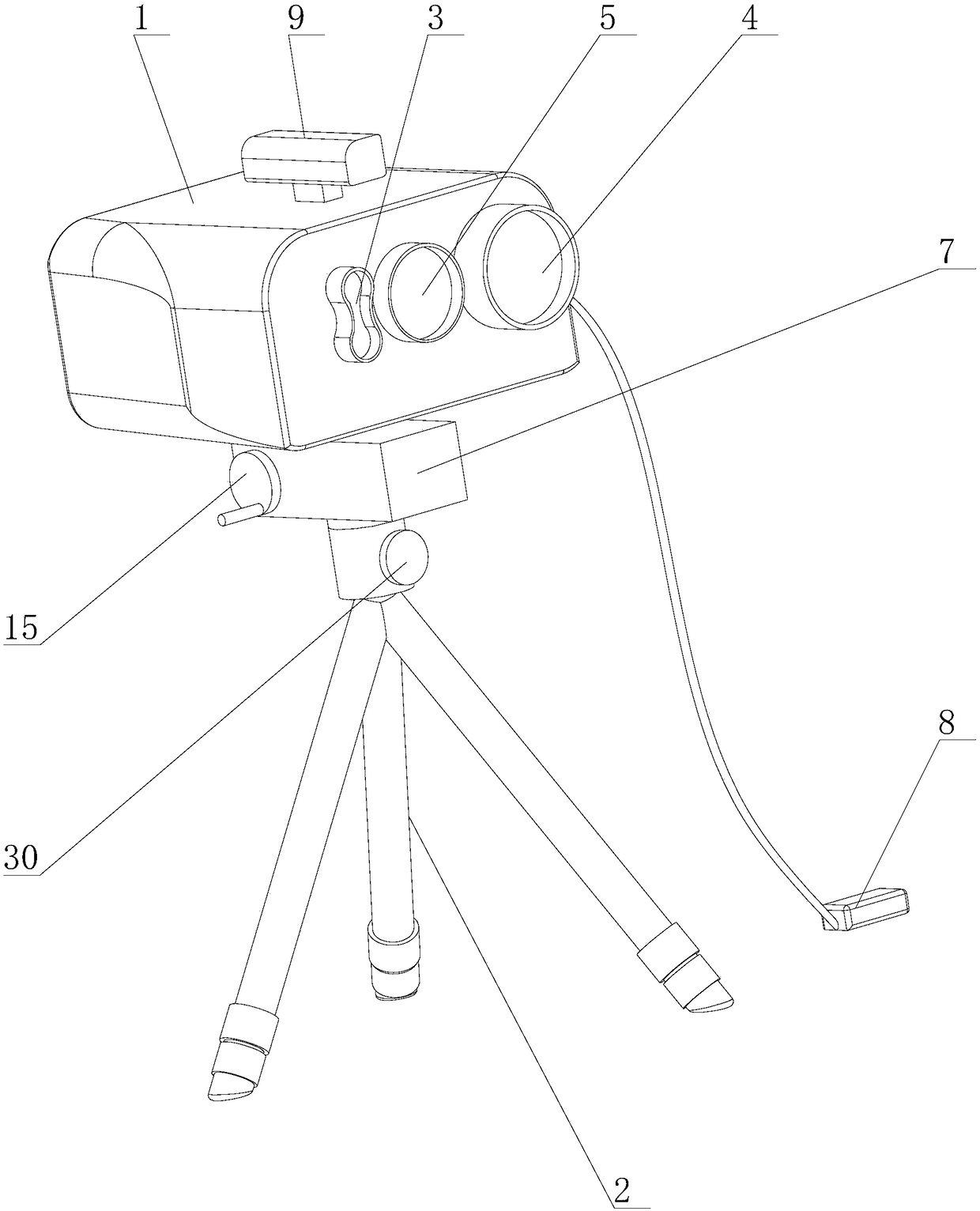
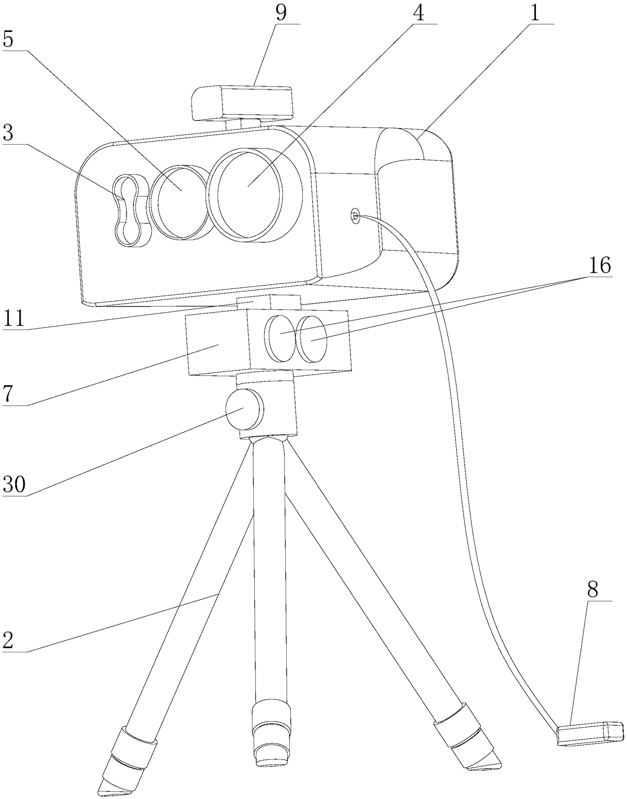
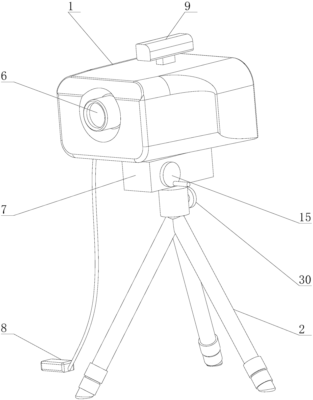

Image

  • Portable remote laser obstacle removal device for foreign matter on power transmission line
  • Portable remote laser obstacle removal device for foreign matter on power transmission line
  • Portable remote laser obstacle removal device for foreign matter on power transmission line

Examples


Embodiment Construction

[0028] The following will clearly and completely describe the technical solutions in the embodiments of the present invention with reference to the accompanying drawings in the embodiments of the present invention. Obviously, the described embodiments are only some, not all, embodiments of the present invention. Based on the embodiments of the present invention, all other embodiments obtained by persons of ordinary skill in the art without creative efforts fall within the protection scope of the present invention.

[0029] Such as Figure 1 to Figure 7 As shown, this embodiment provides a portable remote laser obstacle remover for foreign matter on transmission lines. The main structure includes a body 1 and a tripod 2. The body 1 is supported by the tripod 2. A distance measuring device 3 is provided on the body 1. . Laser 4. The ranging device 3 is used for ranging the foreign objects on the transmission line, and the laser 4 is used for emitting laser light. It also includ...


PUM


Abstract

The invention provides a portable remote laser obstacle removal device for a foreign matter on a power transmission line. The portable remote laser obstacle removal device comprises an engine body, atriangular support, a CCD observation part and a laser beam expander light beam focusing system, wherein a distance measurement device and a laser are arranged on the engine body, an observation display is arranged on the engine body, the laser beam expander light beam focusing system and a laser are arranged on an optical light path, a high-accuracy cloud deck is arranged between the engine bodyand the triangular support, a horizontal rotation control device and a pitching control device are arranged on the high-accuracy cloud deck, and a remote control handle is connected with the engine body via a wire. With the portable remote laser obstacle removal device for the foreign matter on the power transmission line, provided by the technical scheme, single-person portable operation is trulyachieved under the condition that the power of an acting point is ensured, the power conversion efficiency is high, and the action time generated by the laser is short; and the horizontal rotation control device and the pitching control device are used as an aiming system, a high-energy laser beam can be projected to a surface of the foreign matter hung on the high-voltage power transmission lineon ground, and the foreign matter is burnt out or cut off.

Description

technical field [0001] The invention relates to the technical field of laser obstacle removers, in particular to a remote laser obstacle remover for foreign matter in portable transmission lines. Background technique [0002] In the existing technology, the foreign matter removal methods of transmission lines mainly include manual climbing and removal, unmanned aerial vehicle fire removal, insulated arm truck lift-off and picking, etc. However, due to technical limitations, there is a safety risk when the removal instrument is too close to the live equipment , or the work takes a long time, the work intensity is high, and the labor risk is high. The current laser power grid has invested a small amount of applicable remote laser obstacle removal system. Using the traditional carbon dioxide laser radiation principle, the laser tube is large in structure, and the conversion efficiency is low, and the weight of the whole machine is also mentioned. 40-50KG, the laser light path e...

Claims


Application Information

Patent Timeline
Patent Type & Authority Applications(China)
IPC IPC(8): H02G1/02
CPCH02G1/02
Inventor 黄志龙万施霖张裕汉罗新勇
Owner 广东翼景信息科技有限公司
Learn More