Flue gas desulfurizer and flue gas dust collection, desulfurization and wastewater treatment method

A desulfurization tower, flue gas technology, applied in water/sewage treatment, chemical instruments and methods, oxidized water/sewage treatment, etc., can solve the constraints on the construction and upgrading of dust removal and desulfurization devices, the inability to upgrade the space of devices and boilers, and shutdowns or demolishing and rebuilding

Active Publication Date: 2018-10-09
CHINA PETROLEUM & CHEM CORP +1
View PDF6 Cites 0 Cited by
  • Summary
  • Abstract
  • Description
  • Claims
  • Application Information

AI Technical Summary

Problems solved by technology

The above-mentioned wet desulfurization technology includes flue gas desulfurization, desulfurization wastewater oxidation treatment or regeneration unit. The process is long, there are many equipments, and the floor area is large, which seriously restricts the construction and upgrading of dust removal and desulfurization devices. Some devices and boilers are due to lack of There is not enough space to upgrade and renovate, resulting in smoke emission indicators that cannot meet the current national standards and forced to stop work or demolish and rebuild

Method used


Image

  • Flue gas desulfurizer and flue gas dust collection, desulfurization and wastewater treatment method
  • Flue gas desulfurizer and flue gas dust collection, desulfurization and wastewater treatment method
  • Flue gas desulfurizer and flue gas dust collection, desulfurization and wastewater treatment method

Examples


Embodiment

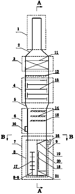
[0082] A flue gas dedusting and desulfurization tower, from top to bottom are the flue gas discharge area 1, the mist removal area 3, the tower area 4, the spray area 6 and the waste water treatment area 7, the flue gas discharge area 1 and the mist removal area 3 It is connected by a cone-shaped diameter 2, and below the demisting area 3 is a tray area 4, and the tray area 4 and the spray area 6 are connected by an inverted cone-shaped diameter 5, and below the spray area 6 is a waste water treatment area 7.

[0083] A wet electrostatic demister 11 is arranged in the demisting area 3, a liquid distributor 12 is arranged under the wet electrostatic demister 11, a tray area 4 is arranged under the liquid distributor 12, and a total of 4 layers of trays are arranged in the tray area 4. A sieve tray is selected; the spray area 6 is provided with three layers of spray pipelines 14, the distance between the spray pipelines 14 is 2m, and the atomizing nozzles 15 are evenly arranged o...


PUM

PropertyMeasurementUnit
heightaaaaaaaaaa

Abstract

The invention discloses a flue gas desulfurizer and a flue gas dust collection, desulfurization and wastewater treatment method. The flue gas desulfurizer comprises a flue gas emission zone, a defogging zone, a tower disc zone, a spraying zone and a wastewater treatment zone from top down in sequence, wherein the wastewater treatment zone is divided into an oxidation flocculation zone and a circulated clear liquid zone by a vertical partition plate I; the circulated clear liquid zone is completely isolated from the oxidation flocculation zone and the spraying zone through a partition plate IIat the top of the circulated clear liquid zone; the vertical partition plate I is provided with a filtering medium; a flue gas pipeline II extends into the oxidation flocculation zone; a plurality groups of flue gas branch tubes are sequentially and horizontally distributed on a flue gas pipeline II from the bottom up inside the oxidation flocculation zone. By adopting the flue gas desulfurizer, flue gas dust collection, desulfurization and wastewater treatment are carried out in one tower, so that the floor space can be greatly reduced, expense of device construction and transformation can bereduced, and device operation cost can be also reduced.

Description

technical field [0001] The invention belongs to the field of industrial waste gas purification, and relates to a flue gas desulfurization tower and flue gas dust removal, desulfurization and wastewater treatment methods. Background technique [0002] Sulfur dioxide and dust are contained in boiler flue gas and flue gas emitted by factories. Sulfur dioxide and dust are the main components of air pollutants. one. [0003] Environmental pollution is becoming more and more serious, smog incidents occur frequently, and the country pays more and more attention to environmental protection. In recent years, a series of environmental protection laws and regulations, national standards, and management methods have been issued. GB 13223-2011 "Emission Standard of Air Pollutants for Thermal Power Plants" stipulates: coal-fired boiler flue gas dust≯30mg / Nm 3 , SO 2 ≯100mg / Nm 3 ;Coal-fired boiler flue gas dust in key areas≯20mg / Nm 3 , SO 2 ≯50mg / Nm 3 . In the "Comprehensive Implem...

Claims


Application Information

Patent Timeline
Patent Type & Authority Applications(China)
IPC IPC(8): B01D53/78B01D53/80B01D53/50B01D53/96B01D47/06B01D50/00C02F1/72C02F1/74C02F1/78C02F1/56C02F1/52
CPCB01D47/06B01D50/00B01D53/502B01D53/78B01D53/80B01D53/96C02F1/5236C02F1/56C02F1/727C02F1/74C02F1/78B01D2251/604B01D2251/404B01D2251/304B01D50/40
Inventor 李磊李欣齐慧敏刘忠生杨秀娜王昊辰
Owner CHINA PETROLEUM & CHEM CORP
Why Eureka
Try Eureka