Multi-stage sequence triggered emergency system capable of automatically shearing tubular column and sealing borehole

An emergency system and pipe string technology, applied in the field of emergency systems, can solve the problems of reducing the hydraulic pressure of the hydraulic system, reducing the shearing capacity of the ram, and not being able to unlock normally, so as to prevent false triggering, improve system stability, and valve types. little effect

Pending Publication Date: 2018-10-09
海一峰深水(天津)技术服务有限公司
View PDF13 Cites 2 Cited by
  • Summary
  • Abstract
  • Description
  • Claims
  • Application Information

AI Technical Summary

Problems solved by technology

[0006] 1. Most ram blowout preventers can only be locked after the completion of well shut-in, otherwise it is very easy to be damaged, resulting in the failure to unlock normally in the later stage. The existing emergency system has not yet specially dealt with this
[0007] 2. The main factor restricting the shearing capacity of the shearing ram is the hydraulic system pressure during shearing, so before or when shearing occurs, it is not appropriate to activate any other functional devices, such as ram locking devices, emergency safety valves, Wellhead connectors, etc., because activating these functional devices will greatly reduce the hydraulic pressure of the hydraulic system, thereby reducing the shearing capacity of the ram, and the existing emergency system has not yet specially dealt with this

Method used


Image

  • Multi-stage sequence triggered emergency system capable of automatically shearing tubular column and sealing borehole
  • Multi-stage sequence triggered emergency system capable of automatically shearing tubular column and sealing borehole
  • Multi-stage sequence triggered emergency system capable of automatically shearing tubular column and sealing borehole

Examples


Embodiment Construction

[0057] The present invention will be specifically introduced below in conjunction with the accompanying drawings and specific embodiments.

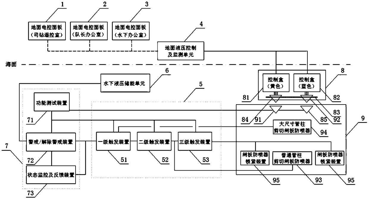
[0058] refer to figure 1 , the emergency system capable of automatically cutting the pipe string and sealing the wellbore triggered by multi-stage sequence of the present invention includes: ground electric control panel (ground electric control panel 1, ground electric control panel 2, ground electric control panel 3), Surface hydraulic control and monitoring unit 4 , lower riser assembly 8 , lower blowout preventer assembly 9 , multi-stage sequentially triggered hydraulic actuator valve group 5 , underwater hydraulic energy storage unit 6 and underwater robot operation panel 7 .

[0059] The structure of each part is described in detail below.

[0060] 1. Ground electric control panel

[0061] There are at least two groups of ground electric control panels, which are recorded as ground electric control panel 1, ground electric control...


PUM


Abstract

The invention discloses a multi-stage sequence triggered emergency system capable of automatically shearing a tubular column and sealing a borehole. The multi-stage sequence triggered emergency systemcomprises a ground electrical control panel, a ground hydraulic control and monitoring unit, a lower drilling riser assembly, a lower blowout preventer assembly, a multi-stage sequence triggered hydraulic execution valve set, a underwater hydraulic energy storage unit and a underwater robot operation panel. The multi-stage sequence triggered hydraulic execution valve set includes a first stage trigger device, a second stage trigger device and a third stage trigger device, and the first stage trigger device, the second stage trigger device and the third stage trigger device are connected in sequence through hydraulic hard pipes and are separately connected with a large-size tubular column shear ram blowout preventer, a common tubular column shear ram blowout preventer and a gate blowout preventer locking device through hydraulic pipelines. The multi-stage sequence triggered emergency system capable of automatically shearing the tubular column and sealing the borehole has the beneficialeffects that (1), the key well sealing actions such as tubular column shearing, borehole sealing and gate locking can be completed step by step; (2), a state monitoring and feedback device and a function testing device are implanted, and the use is more convenient; and (3), valve parts are less and the cost of use is reduced.

Description

technical field [0001] The invention relates to an emergency system, in particular to an emergency system capable of automatically cutting a pipe string and sealing a wellbore triggered by a multi-stage sequence, and belongs to the technical fields of marine deep-water drilling and deep-water oilfield production. Background technique [0002] The harsh marine environmental pollution caused by the deepwater drilling accident in the Gulf of Mexico in 2010 had a huge impact on the entire offshore oil industry. In the subsequent upgrade of international industry standards, it was clearly required that all underwater blowout preventers must be equipped with emergency systems. When underwater blowout preventers When the ground hydraulic supply and ground control ability are lost at the same time, or when the upper riser assembly is accidentally separated from the lower blowout preventer assembly, the emergency system will quickly shear the well string and complete the sealing. [...

Claims


Application Information

Patent Timeline
Patent Type & Authority Applications(China)
IPC IPC(8): E21B41/04E21B33/064
CPCE21B33/064E21B41/04
Inventor 姜波李雪雄华志海何智威
Owner 海一峰深水(天津)技术服务有限公司
Why Eureka
Try Eureka