
Compressed air energy storage CCHP micro-grid structure and operation method thereof

A technology of compressed air energy storage and operation method, which is applied in the field of comprehensive utilization of clean energy, and can solve the problem that the degree of energy cascade utilization is not high, and the complex and changeable working conditions, operation modes, and optimal operation methods of CCHP microgrids are not fully considered. question

Active Publication Date: 2018-10-09
SHANDONG UNIV
View PDF4 Cites 12 Cited by
  • Summary
  • Abstract
  • Description
  • Claims
  • Application Information

AI Technical Summary

Problems solved by technology

Unfortunately, these studies did not fully consider the complex and changeable working conditions and operating modes of CCHP microgrids, as well as the cascade utilization of energy in various operating modes.
[0008] To sum up, in the prior art, the structural design and parameter optimization of CAES are mostly based on its own thermal efficiency or electrical efficiency, and the overall efficiency is rarely taken as the optimization target, and the consideration of thermal energy grade is insufficient, resulting in the cascade utilization of the overall energy. The degree is not high; at the same time, after CAES is connected to new energy and multi-energy complementary CCHP, there is no effective optimization operation method for the complex and changeable working conditions of the system

Method used


Image

  • Compressed air energy storage CCHP micro-grid structure and operation method thereof
  • Compressed air energy storage CCHP micro-grid structure and operation method thereof
  • Compressed air energy storage CCHP micro-grid structure and operation method thereof

Examples


Embodiment Construction

[0066] It should be pointed out that the following detailed description is exemplary and intended to provide further explanation to the present application. Unless defined otherwise, all technical and scientific terms used herein have the same meaning as commonly understood by one of ordinary skill in the art to which this application belongs.

[0067] It should be noted that the terminology used here is only for describing specific implementations, and is not intended to limit the exemplary implementations according to the present application. As used herein, unless the context clearly dictates otherwise, the singular is intended to include the plural, and it should also be understood that when the terms "comprising" and / or "comprising" are used in this specification, they mean There are features, steps, operations, means, components and / or combinations thereof.

[0068] In the new energy multi-energy complementary CCHP micro-grid, it is a common scheduling mode to improve t...


PUM


Abstract

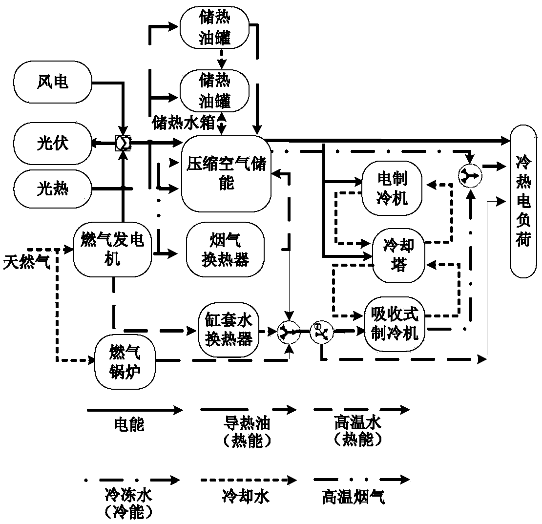
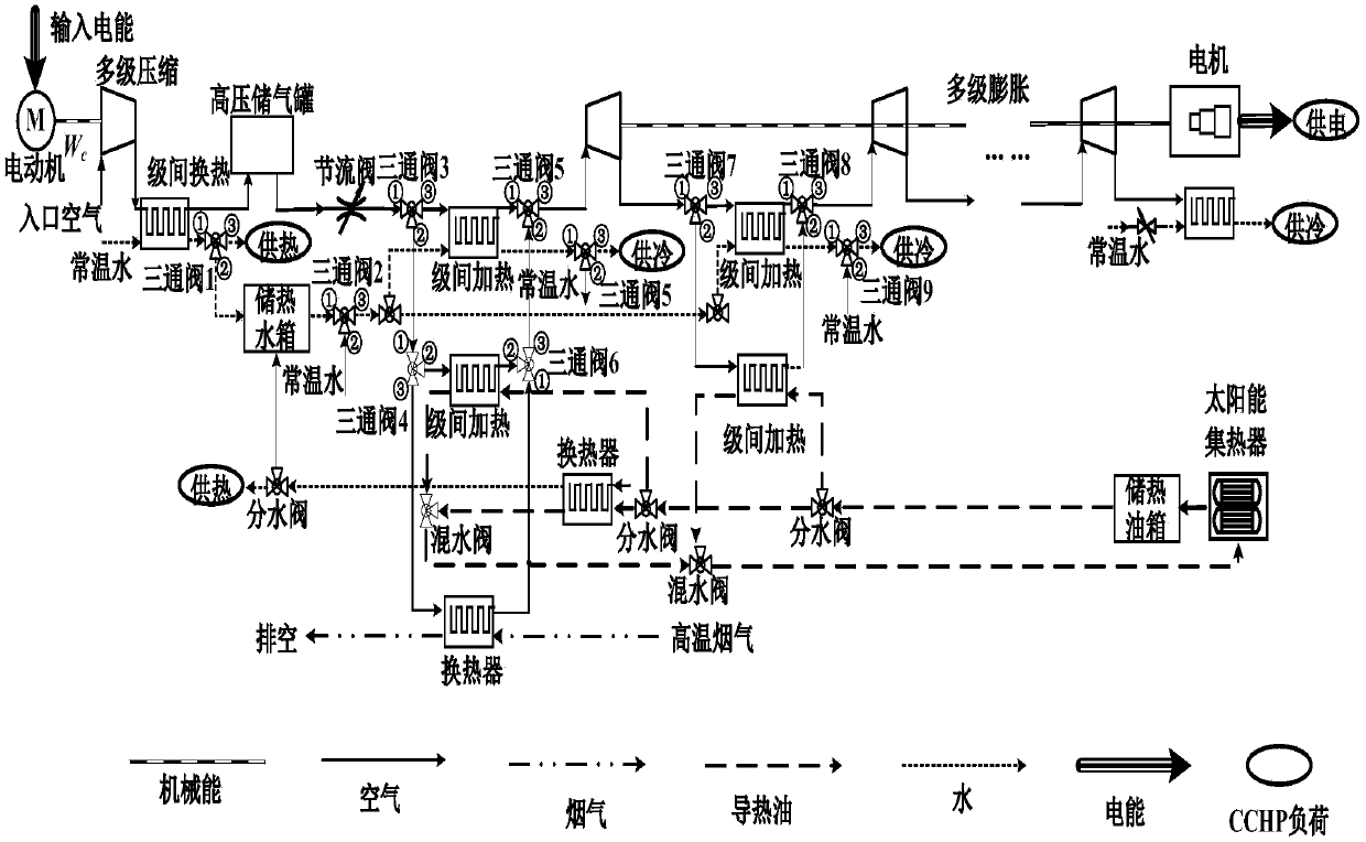
The invention discloses a compressed air energy storage CCHP micro-grid structure and an operation method thereof. The compressed air energy storage CCHP micro-grid structure comprises renewable energy supply equipment, and a combined cooling, heating and power supply unit comprising a gas turbine generator and an absorption type refrigerator, wherein the combined cooling, heating and power supplyunit takes natural gas as the fuel; an adiabatic compressed air energy storage system compresses air to produce the heat energy, the heat energy is stored through the regulation of a three-way valveor directly supplied to a heat user, and the heat energies of different heat sources are absorbed according to the working mode of the system when the energy is released. The A-CAES and the new energyare complemented, a CCHP micro-grid is combined, the A-CAES structure and the main working mode are optimized from the perspectives of flow design and gradient utilization of the energy, the heat source of the regenerative heat is regulated in the A-CAES expansion process by opening and closing a valve, so that various grades of energies in the CCHP micro-grid are reasonably distributed, and thegradient utilization of the energy of a CCHP system is greatly increased.

Description

technical field [0001] The invention relates to the technical field of comprehensive utilization of clean energy, in particular to a structure and operation method of a CCHP microgrid with compressed air energy storage. Background technique [0002] With the energy crisis and environmental issues becoming important constraints on social and economic development, reforming the traditional energy supply system and establishing efficient, reliable and environmentally friendly new energy supply methods have become the energy development strategies of various countries. The new energy multi-energy complementary cooling, heating and power microgrid (Combined Cooling Heating and Power, CCHP) is an integrated energy system based on the principle of energy cascade utilization, which can realize power generation, cooling and heating at the same time. With the rapid development of distributed energy supply technology, energy system control and management technology, CCHP is considered ...

Claims


Application Information

Patent Timeline
IPC IPC(8): F02C6/16F02C6/18G06F17/50
CPCF02C6/16F02C6/18G06F30/20Y02E50/10Y02E60/16
Inventor 张承慧李珂严毅洪明哲
Owner SHANDONG UNIV
Learn More