+/-1100kV direct current voltage divider

A technology of DC voltage divider and voltage equalizing ring, applied in the direction of voltage divider, etc., can solve problems such as premature aging of insulating materials, affecting equipment safety, and insufficient insulation performance, so as to achieve uniform distribution of internal field strength and reduce local Electric field strength, effect of satisfying insulation performance

Inactive Publication Date: 2018-10-09
STATE GRID CORP OF CHINA +3
View PDF4 Cites 7 Cited by
  • Summary
  • Abstract
  • Description
  • Claims
  • Application Information

AI Technical Summary

Problems solved by technology

[0003] At present, the ±800kV ultra-high DC transmission technology is the highest voltage DC transmission technology in China. The existing DC voltage divider can only meet the measurement of DC voltage on the ±800kV polar line, but cannot measure the DC voltage on the ±1100kV polar line.
One reason is that the insulation performance is not enough; another more critical bottleneck is the design of the voltage equalizing ring at the high voltage end
[0004] Due to the concentration of the electric field, material defects or internal partial discharges will occur at the interface between different materials, which will cause premature aging of the surrounding insulating materials at the high voltage end of the DC voltage divider, resulting in a decrease in insulation performance
[0005] At present, the voltage equalizing ring structure of the DC voltage divider generally adopts the implementation mode of a single large ring. Although this voltage equalizing ring can play a certain uniform electric field and suppress corona and electric corrosion, it can only be used at a voltage level of ±800kV When the voltage is raised to the ultra-high voltage level of ±1100kV, a large corona will be generated near the high-voltage terminal, which will affect the safety of the equipment and even cause air breakdown, and its performance cannot meet the requirements
Although increasing the area and volume of the grading ring can improve this problem, it is also accompanied by an increase in the volume and cost of the DC voltage divider

Method used


Image

  • +/-1100kV direct current voltage divider
  • +/-1100kV direct current voltage divider
  • +/-1100kV direct current voltage divider

Examples


Embodiment Construction

[0025] The present invention will be further described below in conjunction with the accompanying drawings and given embodiments, but is not limited thereto.

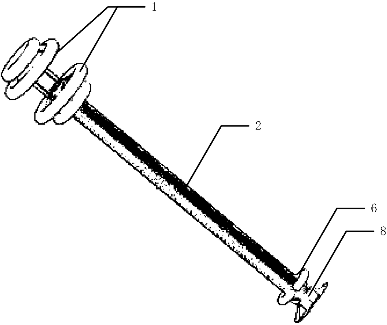
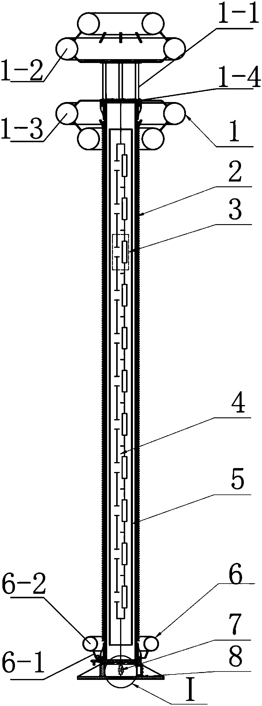
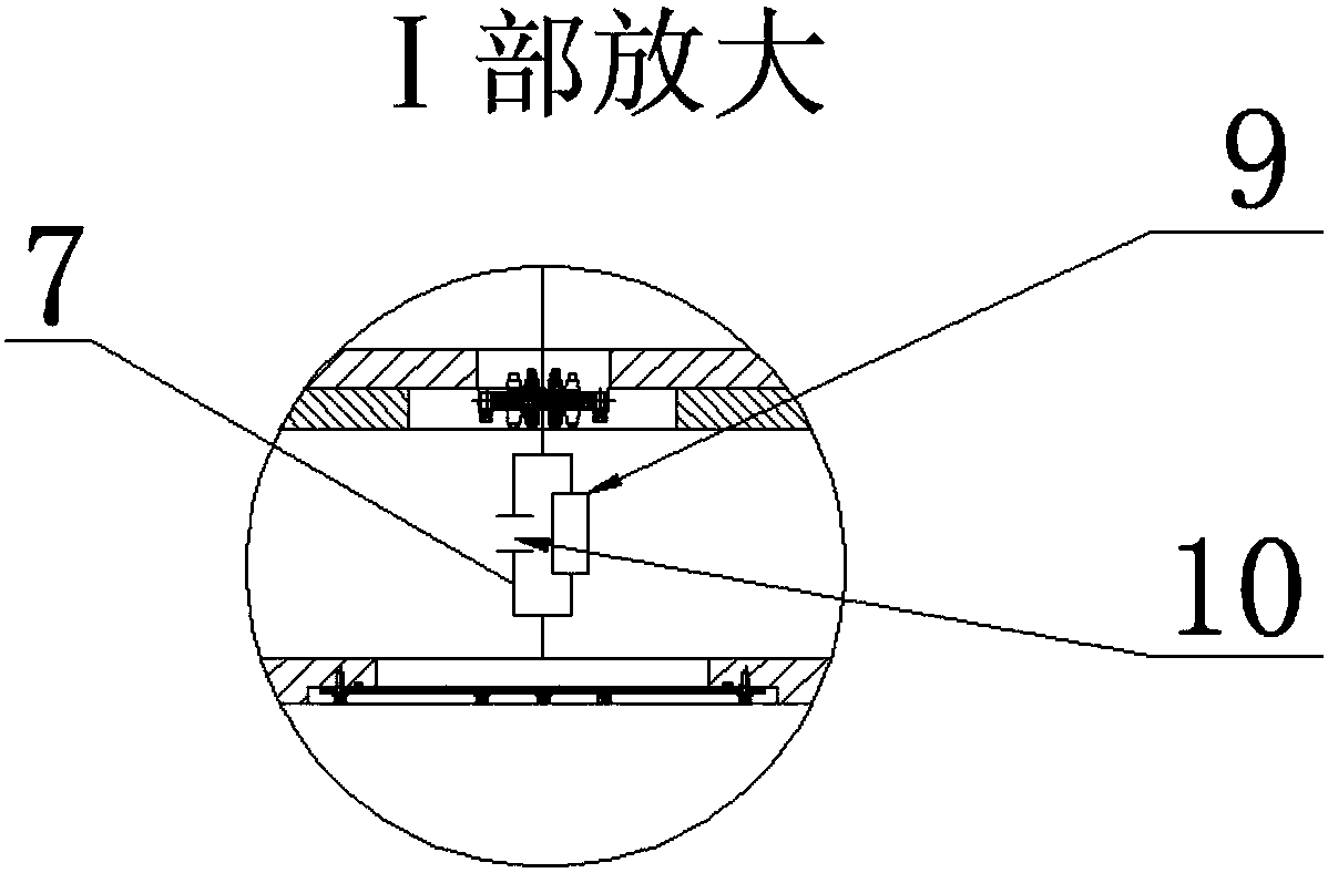
[0026] Such as figure 1 , 2 , 3, a ± 1100kV DC voltage divider, comprising a high-voltage end equalizing ring assembly 1, a high-voltage arm unit 4, a low-voltage end equalizing ring assembly 6, a low-voltage arm unit 7 and a base 8, the low-voltage arm unit 7 It is installed on the base 8, and one end of the low-voltage arm unit 7 is connected to the base 8 (ground terminal); the protection level of the base 8 is IP67.

[0027] It also includes a first insulating hollow bushing 2 and a second insulating inner tube 5, the second insulating inner tube 5 is set in the first insulating hollow bushing 2, and the high voltage arm unit 4 is set in the second insulating inner tube 5 , the base 8 is fixedly connected to the first insulating hollow bushing 2, and the voltage equalizing ring assembly 6 at the low-voltage end is...


PUM


Abstract

In the invention, a high voltage end grading ring component, a high voltage arm unit, a low voltage end grading ring component, a low voltage arm unit and a pedestal are included. The low voltage armunit is arranged on the pedestal. A first insulation hollow casing pipe and a second insulation inner pipe are included. The second insulation inner pipe is arranged in the first insulation hollow casing pipe. The high voltage arm unit is arranged in the second insulation inner pipe. The pedestal is connected to the first insulation hollow casing pipe. The low voltage end grading ring component isarranged on one end of the first insulation hollow casing pipe. The high voltage end grading ring component comprises a first support, two grading ring groups fixed to the first support and a high voltage end terminal. The first support is arranged on the other end of the first insulation hollow casing pipe. The grading ring groups form a spherical or ellipsoidal envelope structure. The two endsof the high voltage arm unit are connected to the high voltage end terminal and the other end of the low voltage arm unit. In the invention, a field intensity near a high voltage end is uniformly distributed and local electric field intensity is reduced.

Description

technical field [0001] The invention relates to a DC voltage divider, in particular to a ±1100kV DC voltage divider capable of measuring 1100kV polar line voltage. Background technique [0002] With the increase of AC transmission capacity, the increase of line distance and the complexity of the grid structure, the stability of the AC system, the limitation of short-circuit current, and voltage regulation have become increasingly prominent. DC transmission has shown more advantages than AC in terms of high-power ultra-high voltage long-distance transmission, cable transmission, and asynchronous networking. DC transmission can connect two AC networks with different frequencies and voltages. At the same time, the DC loss of the line is small, there is no reactive power loss, and the transmission capacity can be large, so it is more economical and reliable. [0003] At present, the ±800kV ultra-high DC transmission technology is the highest voltage DC transmission technology i...

Claims


Application Information

Patent Timeline
Patent Type & Authority Applications(China)
IPC IPC(8): G01R15/06
CPCG01R15/06
Inventor 余军郭贤珊罗苏南刘杰杨洪涛张广泰卢为
Owner STATE GRID CORP OF CHINA
Why Eureka
Try Eureka