Flue gas desulfurization and denitration system and method

A technology for desulfurization, denitrification and desulfurization systems, applied in the field of flue gas desulfurization and denitrification systems, can solve problems such as difficulty in popularization, poor desulfurization and denitrification effects, etc., and achieve the effects of wide application range, good adjustment characteristics, and guaranteed stability

Pending Publication Date: 2018-10-12
南京石博环保科技有限公司
View PDF2 Cites 3 Cited by
  • Summary
  • Abstract
  • Description
  • Claims
  • Application Information

AI Technical Summary

Problems solved by technology

[0009] Aiming at the problems that the traditional semi-dry flue gas desulfurization and denitrification system and method in the prior art have poor desulfurization and denitrification effects and are difficult to popularize, the present invention provides a flue gas desulfurization and denitrification system and method, which combine the rotary spray desulfurization an

Method used


Image

  • Flue gas desulfurization and denitration system and method
  • Flue gas desulfurization and denitration system and method
  • Flue gas desulfurization and denitration system and method

Examples


Example Embodiment

[0068] Example 1

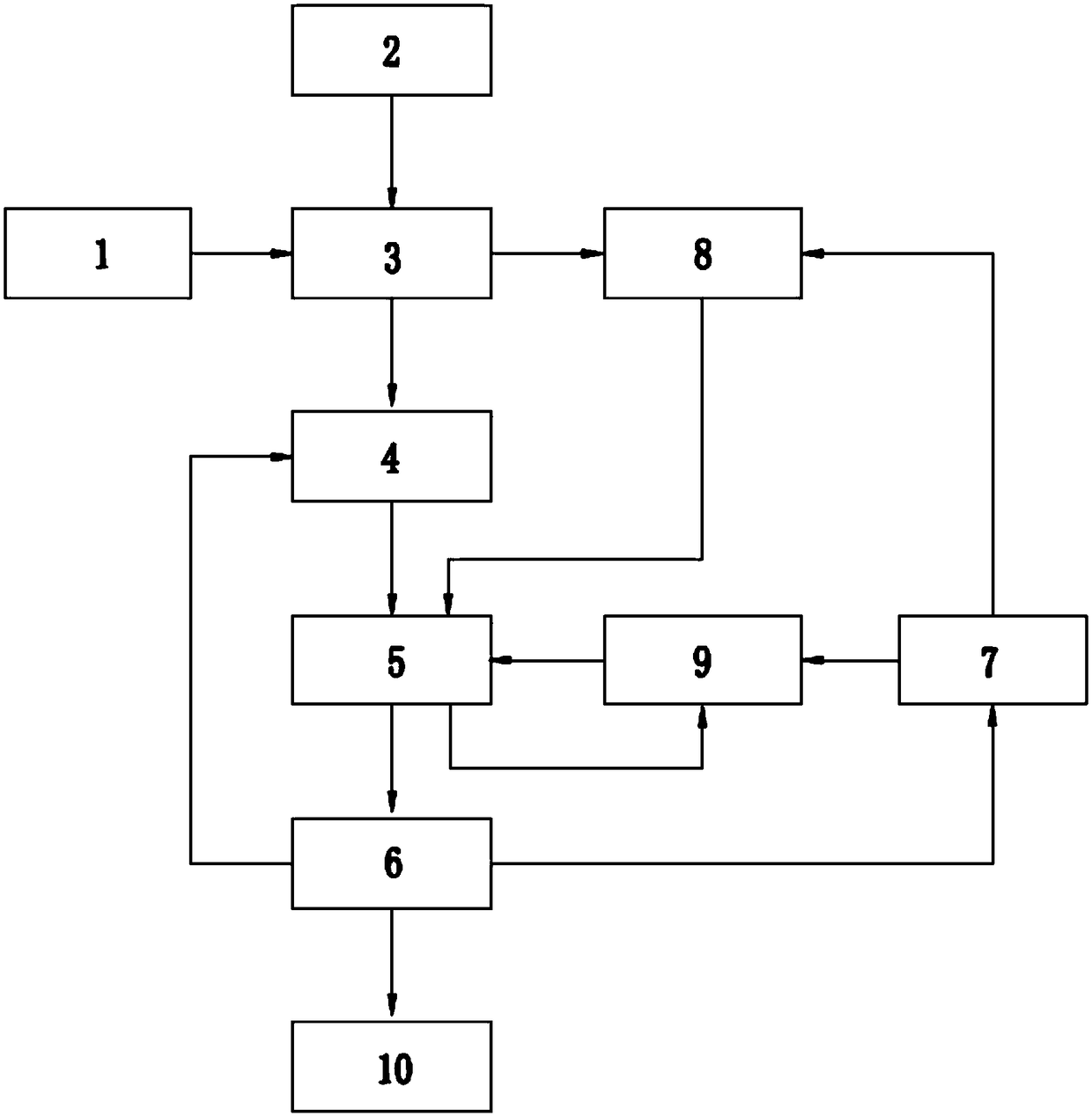
[0069] Such as figure 1 As shown, a flue gas desulfurization and denitrification system includes a pre-dust collector 1, a rotary spray desulfurization and denitrification system 3, an induced draft fan 6 and a chimney 10 arranged in sequence, the pre-dust collector 1, a rotary spray desulfurization and denitrification system 3, and an induced draft fan 6 and the chimney 10 are connected in sequence through a flue, and the rotary spray desulfurization and denitration system 3 is used for preliminary desulfurization and denitration of the flue gas, wherein SO 2 Partially removed, NOx is oxidized to high-valence NO 2 And N 2 O 5 A circulating fluidized bed desulfurization system 5 is provided between the rotary spray desulfurization and denitrification system 3 and the induced draft fan 6, and is connected in sequence through a flue. Most of the unreacted slaked lime in the rotary spray desulfurization and denitrification system 3 The powder enters the circulating...

Example Embodiment

[0077] Example 2

[0078] The basic structure of a flue gas desulfurization and denitrification system of this embodiment is the same as that of embodiment 1. The difference and improvement are that:

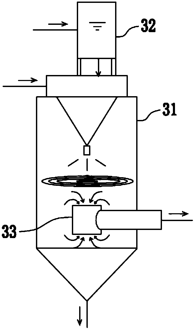
[0079] Such as image 3 As shown, the rotary spray desulfurization and denitrification system 3 includes a rotary spray desulfurization and denitration reaction tower 31 and a self-flowing high-level emulsion tank 32. The self-flowing high-level emulsion box 32 is arranged above the top of the rotary spray desulfurization and denitration reaction tower 31. The forced oxidized slaked lime milk in the self-flowing high-position emulsion tank 32 flows into the high-speed centrifugal atomizer in the rotating spray desulfurization and denitrification reaction tower 31 through the gravity pipe set at the bottom of the self-flowing high-position emulsion tank 32 by gravity, Participate in the oxidation reaction in the rotating spray desulfurization and denitration reaction tower 31 after at...

Example Embodiment

[0084] Example 3

[0085] Such as image 3 As shown, the basic structure of a flue gas desulfurization and denitrification system of this embodiment is the same as that of Embodiment 2. The difference and improvement lies in that, further, the rotating spray desulfurization and denitration reaction tower 31 is provided with two-sided shafts at the bottom of the tower. To exhaust device 33, the axial exhaust device 33 on both sides is a T-shaped structure in which two steel pipes are connected and fixed at 90° to each other. The two steel pipes are vertical along the axis of the rotating spray desulfurization and denitration reaction tower 31. Straight installation, the other horizontal installation, the flue gas enters from the two ends of the vertical steel pipe, and then is discharged from the horizontal steel pipe; the flue gas is axially discharged from the upper and lower air inlets of the axial exhaust device 33 on both sides , It will not affect the rotating airflow in the...


PUM


Abstract

The invention discloses a flue gas desulfurization and denitration system and method, and belongs to the technical field of flue gas processing. The system comprises a pre-deduster, a rotating spray desulfurization and denitration system, an induced draft fan and a chimney, a circulating fluidized bed desulfurization system is arranged between the rotating spray desulfurization and denitration system and the induced draft fan, and a flue gas mixing axial adjustment damper is arranged between the rotating spray desulfurization and denitration system and the circulating fluidized bed desulfurization system; the system further comprises a booster conveying fan, a material conveying pump I and a material conveying pump II. Accordingly, the rotating spray desulfurization and denitration systemand the circulating fluidized bed desulfurization system are combined, step-by-step desulfurization and denitration on flue gas are achieved, and the desulfurization and denitration efficiency is high; due to step-by-step desulfurization and denitration, the system and method can be applied to desulfurization and denitration processing of the flue gas high in sulfur content and nitrate content, and the application range is high.

Description

technical field [0001] The invention belongs to the technical field of flue gas treatment, in particular to a flue gas desulfurization and denitrification system and method. Background technique [0002] With the rapid development of my country's economy, the topic of environmental protection continues to come into view. Flue gas treatment is a general direction in the field of environmental protection and has received more and more attention. In recent years, the emission indicators of exhaust gas have become more and more stringent. A 2018 government report states that SO 2 , NOx emissions should be reduced by 3% compared with 2017, and PM2.5 in key areas should continue to decline. Under the guidance of a series of policies, the vast majority of coal-fired power plants have installed denitrification, desulfurization and dust removal devices. In the future, promoting the treatment of flue gas from coal-fired boilers and non-electric industries will be an important task of...

Claims


Application Information

Patent Timeline
IPC IPC(8): B01D53/80B01D53/60B01D46/02
CPCB01D53/80B01D46/02B01D53/60B01D2251/404B01D2251/604B01D2258/0283
Inventor 马贵林周英贵陈思同黄冰冰
Owner 南京石博环保科技有限公司
Why Eureka
Try Eureka